1

I am having trouble wrapping my brain around this power transformer circuit. I must be missing something very fundamental, so I apologize in advance for that.
enter image description here

Can someone explain to me why the center tap on this schematic does not have to be rectified? Also, if the center tap is 0v, how is it supplying power? It appears to be powering all of the tubes except the final 807s. The transformer is a 300v. I'm not sure if that means 150-0-150, or 300-0-300.

I must be missing something simple.
JRE
  • 67,678
  • 8
  • 104
  • 179
McMurdo
  • 117
  • 7
  • 1
    Your error is in thinking the centre-tap is at zero volts. It is at half voltage. The winding **ends alternately** are clamped to zero volts. The centre-tap is full-wave half voltage (+) – glen_geek Dec 18 '18 at 23:56
  • The EL84 datasheet I just looked at suggests a max of about \$250\:\text{V}\$. So I'm pretty sure the transformer is a center-tapped \$300\:\text{V}_\text{RMS}\$ (or, as you write, \$150-0-150\$.) The ground symbol on the schematic is the negative rail. The center-tap is the mid-point rail. – jonk Dec 18 '18 at 23:56
  • Excellent. Thank you both for your help. This clarifies a lot. Any idea why the center tap does not need to be rectified? Or is it being rectified in some way that I am not seeing? Thanks again. – McMurdo Dec 19 '18 at 00:30
  • It is being rectified in a way that you are not seeing -- basically, the way that @glen_geek explained. It may help to grab a pencil and paper and draw out the rectifier and transformer, then redraw it with the transformer replaced with a pair of 300V voltage sources in series, minus to plus, then redraw it *again* with the voltage polarities reversed. That's how I have to do it every time, although with time I've learned to do it in my head. – TimWescott Dec 19 '18 at 00:41
  • Thank Tim Wescott. I drew it out three times like you suggested. Something just isn't clicking in my head. I'm not seeing how that is DC coming out of the center tap without going through a rectifier. Seems like it would be 150VAC. Is the center tap being rectified because the entire secondary (300v) is going through the bridge rectifier? – McMurdo Dec 19 '18 at 02:09
  • I do not have enough time to post a proper answer yet, but your interpretation *isn't false*. The center tap *is* at 150 VAC, *relative to the bottom of the transformer*. So if we define the center to be 0V, then each branch of the transformer has 150 VAC accross it. Note that as the "top" of the "bottom" part is at ground potential, the voltage at the bottom will be in antiphase relative to the top. At 90°, think about it : – Sachiko.Shinozaki Dec 19 '18 at 06:59
  • Relative to the bottom : Bottom at 0V, middle at 150*sqrt(2), top at 300*sqrt(2). Now relative to the center : Bottom at -150 * sqrt(2), center at 0V, top at 150 * sqrt(2) – Sachiko.Shinozaki Dec 19 '18 at 07:00
  • Thank you Sachiko Shinozaki. I understand how it is being rectified by the left two diodes in the bridge now. Thanks to ALL for your help! – McMurdo Dec 19 '18 at 18:33

1 Answers1

1

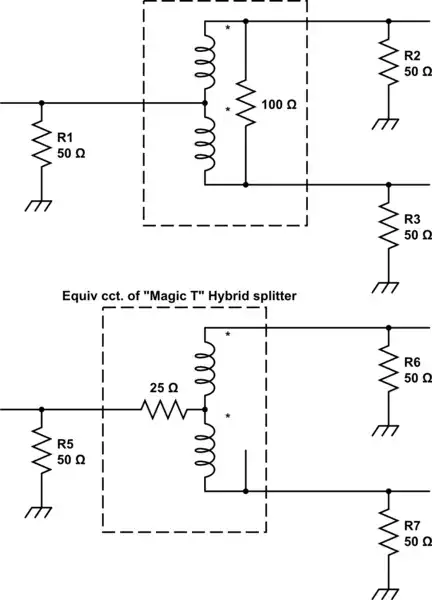
While one half of AC period, two bridge rectifier diodes are open (see effective chematic below). So, one end of secondary is connected to ground and another - to 300 V output capacitor. At the same time, center tap produces half of full secondary voltage.

On another half of AC period, picture is almost the same, just anoter two diodes of bridge rectifier are opened.

So, center tap produces fully rectidied waveform with half of full secondary amplitude.

schematic

simulate this circuit – Schematic created using CircuitLab

Eugene K
  • 918
  • 5
  • 9