0

Im simulating LC circuit in LTSpice: enter image description here
It's tuned at resonance at 1 MHz in the transient response simulation plotting the source and R1 current. Both of which are equal in amplitude 600mA but with a 180° phase difference.

In this picture we see the ac transient response for curent in R1 with a value of -20dB at 1 MHz which is considerable: enter image description here
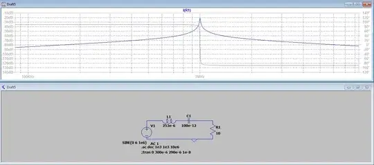
So the question is if the attenuation is -20 dB, besides the phase difference, why is the R1 and source current amplitude the same and/or what am I missing?

  • Related: [Why am I getting negative base current in LTSpice simulation?](https://electronics.stackexchange.com/q/206055/6334) – The Photon Dec 12 '18 at 16:53

1 Answers1

0

what am I missing?

This: -

In an AC simulation, 0 dB is the default reference value for the voltage source and that strictly speaking means 0 dBV or 1 volt RMS. So, when your tuned circuit is fed precisely the frequency that resonates it, all of that 1 volt RMS becomes applied to your 10 ohm resistor. That generates a current of 0.1 amps RMS or, put another way -20 dBI or loosely put, in terms of the vertical scale on your graph you have it peak at -20 dB.

if the attenuation is -20 dB....

It isn't; the current through the 10 ohm resistor is -20 dBI or 100 mA RMS (as one would expect when 1 volt RMS is applied through a resonant series tuned circuit).

Andy aka
  • 434,556
  • 28
  • 351
  • 777
  • Thank you! Then not to post a new question, so I'm assuming that the amplification coefficient is not affiliated with phase difference. But then why is there a phase difference if in the ac current response for R1 if at resonance there is 0°? – Raitis Bērziņš Dec 12 '18 at 15:24
  • Just look at the 2nd graph in your question - phase angle is specified down the right axis and, at pure resonance it is zero degrees. – Andy aka Dec 12 '18 at 15:26
  • I don't think this answers why the phase is shown as 180 in the transient simulation but somewhere between +90 and -90 in the AC simulation. – The Photon Dec 12 '18 at 16:53
  • In the transient simulation, when currents are plotted, it is the current going into pin 1 that is the default current to plot so, if the resistors pin 1 is connected to the ground node then it will be displayed as 180 degrees shifted @photon but I’m sure you knew this! – Andy aka Dec 12 '18 at 19:11