Here is a simulation of the results of moving 1volt signal over a 15cm trace that is 1/16th inch above the Ground plane. I assume the source and load resistances are 1,000 ohms; high impedance nodes (your 15cm trace) are very vulnerable to Electric Field Interference EFI; the Loop Area (that 15cm distance and the 1/16" height) are very vulnerable to Magnetic Field Interference HFI.
Also, currents flowing in the Ground impedance will inject errors.
Here is the resultant display (with Gargoyles enabled at the top right--- HFI, EFI, GPI):
The Signal Noise Ratio is only 19.6dB as shown in the top right, computed at 7MHz Frequency Of Interest. Given the assumptions about the various interferers, simply call that 20dB +-5dB. Look down the right column, and find the Aggressors (RSS combined) are 18 milliVoltsRMS; notice the Signal is only 175mVRMS because of the 6dB division and the 1volt source PP.
What are the Gargoyles (the interferers, the aggressors)?
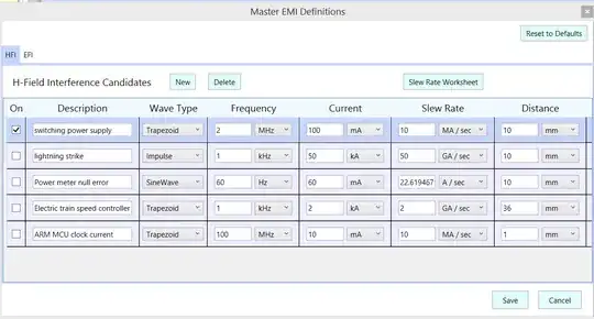
HFI magnetic field is a switching regulator, located only 10mm from the 15cm trace, with slewrate of 10 Million amps per second.
EFI electric field is 3 fold; the dominant interferer is a microcontroller at 10mm from the 15cm trace, with slewrate of 2.5GigaVolt per second. There are secondary EFI sources, as you can see in the table of Analysis Details (that Text display), from 60Hz power wiring that are by default located only 1mm (1 millimeter) away from the 15cm trace.
GPI ground interference is 0.1 amps flowing thru 0.038 ohms of Ground/RETURN path.
The trace is 15cm long, 1mm wide, placed 1/16" above the Ground. The return path is (in this version of the tool) modeled as the same resistance as the signal, to emphasize the danger to SNR if you have Ground currents.
To define the inter-stage trace (15cm long), enter the Wiring Wizard (click on TRC between the stages) and edit the default 10mm length to be 150mm.
And here is the built-in (it is editable) HFI magnetic field aggressor table. Notice only the switching regulator is selected.