5

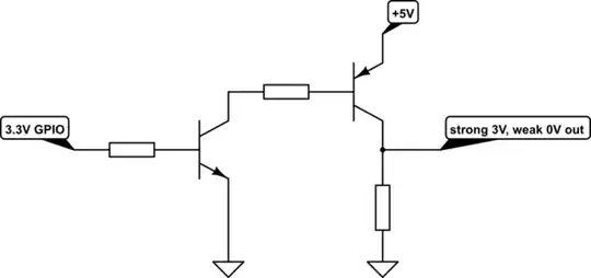
I was trying to step up the output of a 3.3V microcontroller pin to 5V for communication with another device. I wanted to do it with a single bjt, and found a good design for doing that here

Single transistor level up shifter

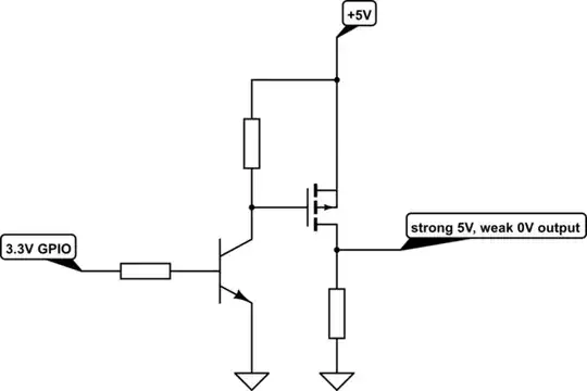
That design works fine and I've moved on with the project, but it left me with a question: Before I went looking for a design online, I assumed I could just flip the resistor on a standard logic-inverting level changer from the high side of the transistor to the low side. i.e. I tried this

schematic

simulate this circuit – Schematic created using CircuitLab

It seemed like a pretty straightforward switch. At LOW input, I thought the transistor would be off and the output pulled to 0V, and at HIGH the transistor would be active and connecting Vout to 5V. The HIGH part of the plan didn't work, though. A 3.3V input to the base brought Vout into the neighborhood of 2V, with 3V dropped across the transistor itself.

I don't have a lot of breadboarding experience, so I'm sure there's a simple explanation that I'm missing here. If anyone could enlighten me as to what's going on, it would be much appreciated!

kb4444
  • 93
  • 1
  • 1
  • 4
  • 3
    The base is supplied from \$3.3\:\text{V}\$, but through \$R_1\$ which will drop some voltage leaving the actual base voltage still lower. The emitter "follows" the base voltage, but is one diode drop below that. So you already know that the base is less than \$3.3\:\text{V}\$ and that the emitter must be about \$700\:\text{mV}\$ less than even that. So there is no way it will connect the \$5\:\text{V}\$ to the emitter! – jonk Dec 08 '18 at 20:45
  • 1
    @jonk, that's in fact the answer. – Janka Dec 08 '18 at 20:45
  • @Janka No. It just explains a result. I guess I'm actually kind of unsure what would be an answer, which is why I'm not attempting one. But perhaps you are right, too. I just don't know. (edited.) – jonk Dec 08 '18 at 20:48
  • You can use a single transistor inverting level shifter, if it is acceptable to invert the signal. But the emitter would be grounded, and the resistor would be in series wit the collector. – user57037 Dec 09 '18 at 05:36

1 Answers1

2

The simple explanation is, no matter what you do, the voltage between base and emitter in a conducting bipolar transistor is always around 1V. So, if your base is at 3.3V, the emitter is around 2.3V. All the rest of the voltage (times current) is turned into heat in the transistor, so be careful.

If you want high-side switching, for example to power something controlled by your I/O, you have to use a PNP transistor. In a PNP, the current directions are reversed so we can now connect the emitter to +5V and the collector to the output.

schematic

simulate this circuit – Schematic created using CircuitLab

As soon the GPIO is 3.3V, the NPN opens. Its collector current is the (negative!) base current for the PNP, which makes that one open, too. The output is at roughly 3V. Not much of an improvement, but if you used an input voltage of 12V, the output would be at 10V, while it was still at 2.3V with your circuit.

A better solution with less voltage drop involves a P-Channel enhancement MOSFET.

schematic

simulate this circuit

The typical voltage drop over a small signal MOSFET is as low as 0.5V, for power MOSFETs much lower. (Unlike the bipolar transistor, which is a current-controllable current source, a MOSFET is basically a voltage-controllable resistor, so it's current-dependent.)

Janka
  • 13,636
  • 1
  • 19
  • 33
  • 1
    How did you get 3V at the output of the first schematic? It should be about 4.8V. – Chupacabras Dec 08 '18 at 22:19
  • 1
    In simulation I get close to 5V too. If you pick your resistors such that both transistors are driven to saturation, the output would be 5V minus the saturation voltage of the PNP transistor. – Hearth Dec 09 '18 at 01:11
  • if it were't for your misconceptions about the first circuit this would be a good answer. – Jasen Слава Україні Dec 09 '18 at 01:29
  • Why did you say "no matter what you do, the voltage between the base and emitter of a conducting bipolar transistor is always around 1V?" The usual numbers given are 0.6 or 0.7V. It won't be at 1V unless it is in deep saturation. – user57037 Dec 09 '18 at 05:34
  • 1
    Feel free to edit. – Janka Dec 09 '18 at 13:12