4

I'm using an 8 output DAC (LTC2666) to control synthesizers via mono 3.5mm jack connections. It works fine most of the time but every once in a while, plugging in a jack into the synthesizer will break the DAC in all sorts of random ways, often requiring a power down.

Is there a proper way to protect my circuitry against whatever glitches are induced by the mechanical nature of plugging in a jack?

schmop
  • 125
  • 6
  • 5
    3.5mm jacks short out the contacts while being plugged in. If you're able to use a different connector, that would probably be best, but you should be able to deal with this other ways as well. – Hearth Dec 03 '18 at 17:10
  • 1
    @Hearth Unfortunately 3.5mm and 6.5mm are the industry standards for analog inputs on synthesizers – schmop Dec 06 '18 at 11:15
  • 1
    Sounds like it goes latch-up due to overcurrent. Maybe if you provide a simplified schematic, some analog guru could suggest an alternative way of driving the signal. Or possibly add some external current limit that kicks in before the IC gets angry. – Lundin Dec 06 '18 at 12:11
  • 1
    As noted, if you post a schematic, we may be able to suggest circuitry to deal with the issue. – Peter Smith Dec 06 '18 at 14:55

4 Answers4

4

Generally speaking, the problem that you describe is often easily cured by adding a resistor in series with the signal. Resistor value is dependent on what the load impedance is but is often in the range of 22R to 100R.

Higher value is better but the tradeoff is the voltage drop caused by that series resistor and the load impedance.

The series resistor does two things:

1) limits peak current during short-circuit conditions.

2) minimizes the chance of latch-up if there is significant ground voltage difference between the two devices being connected as you are plugging one device into the other.

It won't cost you anything to see of that helps or eliminates your problem.

Dwayne Reid
  • 23,390
  • 2
  • 35
  • 67
2

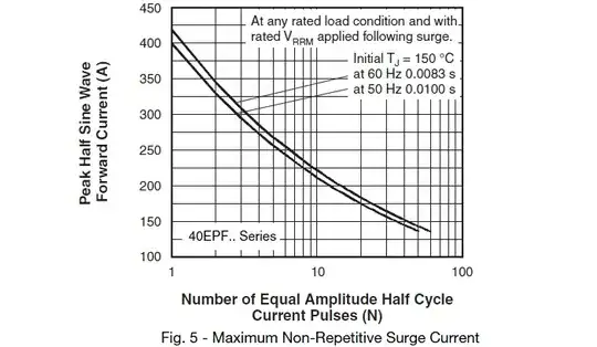
The short circuit current for the outputs has current limiting for overload conditions as you can see in page 7

Note 6: This IC includes current limiting that is intended to protect the device during momentary overload conditions. Junction temperature can exceed the rated maximum during current limiting. Continuous operation above the specified maximum operating junction temperature may impair device reliability.

Shorting the outputs is unlikely to be the source of the failure, since the output current is limited at 45mA, even in the worst condition with V+, V- = 15V the short circuit will generate around 675mW for the short time of plugging, not enough to heat up the chip. Tough, this might happen if you keep multiple outputs shorted or even one for a long time ( half inserted) which I doubt you do. If you suspect this happens then put some kind of thermal fuse coupled with your DAC to shut down the board when to hot.

A jack connector will first make contact between male plug hot wire and female connector ground. If you don't have a common ground while plugging then the different ground potential of the synth might bring the output outside of the limits allowed V+ +1.4V and V- -1.4V. And this can burn your DAC instantly.

To make things worse this can happen even with unpowered DAC and synth.

To avoid the output to be pulled outside of the V+ V- range while DAC is powered you can use two zener diodes as in the image:

schematic

simulate this circuit – Schematic created using CircuitLab

The zener voltage value must be higher than max output voltage and lower than the supply voltage (positive for D1 and negative for D2). This works only when the DAC is powered but it can be implemented outside of the circuit board (might be even inserted in the jack plug).

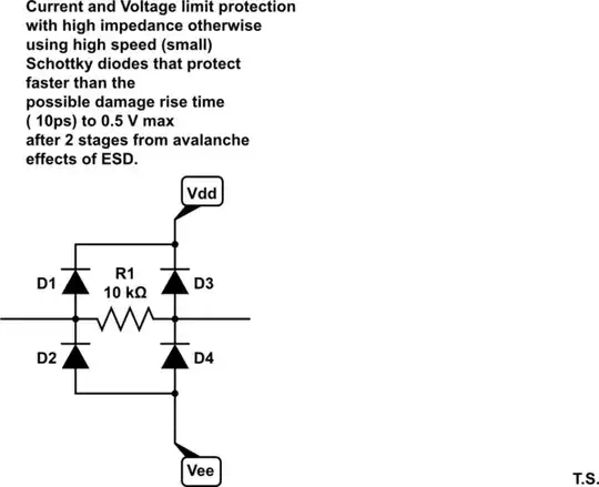
To protect even when DAC is off you will need clamping diodes and access to V+ and V- like in this schematic:

schematic

simulate this circuit

D1 and D2 will keep the output voltage between V+ +0.75V and V- -0.75V.

D3 and D4 will prevent the output to pull V+ or V- above their maximum values of +-16.5V , the zener value must be less than 16.5V but higher than source V+ for D3 and V- for D4.

Also, if some other chip is powered from V+ or V- then take in consideration it's maximum voltage to.

Dorian
  • 2,546
  • 2
  • 11
  • 20
2

If you can remember to touch the case ground while holding the plug before insertion, you can avoid all incidents.

It is a "tribo-electric ESD event", not a mechanical disturbance.

The plastic insulation on the cable jacket itself is often the charge carrier that can discharge an overvoltage that can crowbar a CMOS IC from the input exceeding the supply rails.

If the cable is plugged in the other end already, there is less chance of an ESD even but often audio equipment is not earth grounded by a 1M resistor. It is either floating or earth grounded which is actually worse for discharge currents but possibly better in some cases for audio shielding.

Generally, sensitive CMOS outputs and Inputs are protected with dual-rail Schottky shunt diodes reverse biased to the normal input range. Another pair may be cascaded for extra protection or simply a series Resistance to current limit the discharge so that the diode voltage rise can clamp the transient effectively. CMOS is designed for the 100 pF HBM or human body model "finger" but cables can be 100pF/m or more.

Ultimately it is not the kV that causes latchup but the series current * resistance rise outside the dual rails ( Vdd,Vss or Vcc, Vee) and the resistance ratio with respect to the diodes.

schematic

simulate this circuit – Schematic created using CircuitLab

  • Maybe fix add 10k Series R to all unprotected ports
  • Better fix , add Diodes + R
  • Best fix , Add 2 stage diodes + R

The series R can be reduced to 1% of known input impedance but if the OP does not want to modify every synth to add this each port, then using my initial suggestion is the way to go.

In production our techs used to blow SCSI ports with long floating IO cables dragging on the floor making connections and we were successful to eliminate the issue using this sensible approach.

Tony Stewart EE75
  • 1
  • 3
  • 54
  • 182
0

I would suggest a simple buffering emitter follower between DAC output and jack plug. \$ Q_1 \$ has a high \$ \beta \, (>500)\$ to make its input impedance high \$ ( >1 \,M \Omega ) \$ in order to keep \$ R_1 \$ from dominating and high enough to be able to use a small decoupling capacitor on the input. Using a low noise type for \$ R_1 \$ is recommended. Assuming the DAC has a relatively low output impedance, the noise generated in \$ R_4 \$ and \$ R_5 \$ would be 'shorted' out by this. Further the base bias current gives about \$ 0.2 V \$ additional voltage drop across \$ R_4 \$.

schematic

simulate this circuit – Schematic created using CircuitLab

joe electro
  • 271
  • 1
  • 4
  • 1
    If I'm not mistaken, this is for audio. In my case the DAC is not sending audio but a parameter control signal that shouldn't be biased. – schmop Dec 08 '18 at 16:54