12

We've been using ATmega48/88/168/328 microcontrollers successfully for many years in many of our products. We have now considered to switch from the A and PA variants to the new PB variant (because we will need the extra pins, timers and UARTs in new products, because it's become cheaper, and because it seems the old variants will be discontinued), so we switched out an ATmega328A with an ATmega328PB. It seems to go haywire very often after power interruptions. Such problems never ever occurred with the old variants.

Regular power interruptions are normal for the usecase of our products. We use a switching power supply (like this one) set to 5V, and have capacitors in the 220µF range on the ATmega's VCC, to keep the SRAM alive for power interruptions in the range of several minutes, to store internal states which are not mission critical but significantly increase user experience by being instantly available upon a restart (these states change often enough to make EEPROM unsuitable). This has always worked.

However, with the new ATmega328PB, after a power interruption, the chip resets without a reset condition being found in MCUSR, and the clock seems to go haywire.

  • the brown-out detector is set per fuse. We tried every available bodlevel, the bug happens on all of them.
  • we use external 20 MHz, also set correctly per fuse.
  • we tried 3 different chips, so it wasn't a single soldering or other hardware failure.

After the bug happens, the clock often sets to 2.5x slower speed, indicating that the mcu is being clocked by the 8 MHz internal oscillator. However, sometimes the slowdown is around 6x. This means it can't be a software bug changing the clock divider, as I cannot set the fuses from software, and the clock divider cannot divide the clock by 2.5 or by 6.

So, my first suspect was the new Clock Failure Detection fuse. However, no matter if it's turned on or off, the behavior remains the same.

To rule out software peculiarities, I wrote a simple test program from scratch, which does nothing else but toggles an output with 100 Hz from a timer interrupt, and indicates with LEDs after each restart which reset conditions were activated (as read from MCUSR). The rest of the hardware was also removed, only the mcu and the regulator are there (and the indicator leds with series resistors).

The results

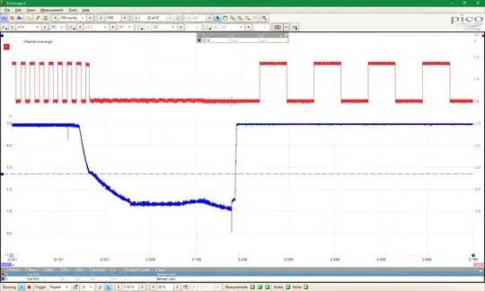
Roughly 2/3 of the time, nothing interesting happens. After the power interruption, the mcu resumes its job, both the brown-out reset and power-on reset indicators lit up.

(on the image, red is the toggled pin, and blue is VCC. On this image, the 2.7 V bronwn-out is clearly visible. I made the same tests with the other brown-out settings, the results are exactly the same, so I will omit those pictures)

it restarts fine

Roughly 1/3 of the time, the aforementioned bug occurs, and when the power is back again, none of the brown-out reset and power-on reset indicators are lit up! The output is different, as if the mcu was ticking with a strange clock. It's not chaotic, however, it keeps ticking with the same frequency.

it restarts in a crazy state

Interestingly, in this situation, the brown-out detector seems to be completely inactive, because after the next power interruption (where the correct clock is sometimes restored, sometimes not), it is clearly visible that the output keeps toggling well after the brown-out level has been passed. In such situations, the clock sometimes gets faster, other times it gets slower:

No brown-out, clock gets faster No brown-out, clock gets slower

During these tests I used 16K CK/14CK + 4.1 ms for the start-up delay (but the 65 ms delay doesn't avoid the problems).

Here is a picture zoomed in, where you can clearly see that the VCC reaches a stable state at 5 V in under 2 ms:

successful start, zoomed in

In the above picture, the mcu started correctly.

Interestingly, when it doesn't, the supply voltage gets up to a stable 5 V even sooner (it seems many parts of the mcu don't power on, so it draws less current during the startup)

Below is an image from an unsuccessful start:

unsuccessful start, zoomed in

Please note, that the software starts running after more than 85 ms after the supply voltage has been stabilized, instead of the 10.5 ms required otherwise. The fuses for the startup delay are still the same, 16K CK/14CK + 4.1 ms.

What's also interesting to note, is that after the supply was turned off, the VCC stabilizes at around 1.1 to 1.2 Volt (the old, ATmega328A variant went down to around 0.6 - 0.7 V). It keeps that for several minutes. If I wait long enough (on the order of half an hour or more), the mcu always starts correctly! So it seems the problem is that there is 1.1 Volt around, which, according to the datasheet, is not guaranteed to be enough for a power-on reset. But it should be enough for a brown-out reset!

Except for these situations, the brown-out detector works fine. It's visible on the first image (the output signal stops when the bodlevel has been reached, and the voltage drop slows down, as parts of the mcu are shut down). I did tests when I reduced the VCC to slightly below the bodlevel and let it climb back again, the mcu always restarted correctly under such conditions, with only the brown-out reset indicator being lit up.

Did I miss something obvious, or does the ATmega328PB have a serious bug in its brown-out detector?

EDIT:

Interestingly, the above problems only arise when I interrupt the supply before the regulator. If I interrupt it after the regulator (or use a lab power supply), the problems never happen. As if the shape of the rising voltage caused the problems. However, as you can see from the last image, the voltage rise is quite nice and it stabilizes quickly.

EDIT 2

I tried it out with 16 MHz instead of 20 MHz, but the exact same problems happen.
vsz
  • 2,554
  • 1
  • 17
  • 32
  • Have you contacted Atmel or looked into their erratas? In this day and age IC design mistakes are quite common. – Edgar Brown Dec 01 '18 at 18:41
  • I have looked through the erratas (didn't find anything in this direction), and we are considering contacting Atmel, but not before making some more tests and looking around a little more. – vsz Dec 01 '18 at 18:42
  • 3
    By my experience don't waste time before contacting the manufacturer or using their forums. You have made more than enough debugging to present a very strong case. With much less than that, TI sent me their internal (unpublished) errata for one of their ICs that documented our issue. – Edgar Brown Dec 01 '18 at 18:46
  • My two cents worth: I have seen problems with other CPUs if the power rises too quickly. Some manufacturers specify a maximum rise time but more often this is not mentioned. – Oldfart Dec 01 '18 at 19:03

2 Answers2

3

I don't think it is a bug with the brown-out detector, but how you use the chip.

As you said yourself, the power-on reset threshold 1.1 V is not reached if power is just briefly removed and connected, so there will be no POR.

Brown-out detector can't help here much either. You are using the AVR at 20 MHz, and this requires the supply voltage to be 4.5 V or above, or you are violating the specs. And BOD does not guarantee that it will trip at 4.5 V, it's typically less than that, say 4.3 V. So even before BOD triggers, there is no guarantee in what state the AVR ends up but the BOD should trigger, except that it may not work due to your 20 MHz clock. When the voltage starts to rise again, the BOD deactivates before supply voltage is at a safe 4.5 V level again. If it was triggered correctly. The start-up delay time should be then set to high enough that the voltage has a change to rise from BOD deactivation level to 4.5 V before the internal reset is released.

But it all may fail because it just needs at least 4.5 V to run at 20 MHz. The AVR datasheet does mention that if internal reset system is unsuitable then use an external reset chip, and in this case it looks like it would solve your issues to reset the AVR before voltage drops to 4.5 V.

Transistor
  • 168,990
  • 12
  • 186
  • 385
Justme
  • 127,425
  • 3
  • 97
  • 261
  • I assumed the BOD doesn't use the processor itself but it's a dedicated hardware. Maybe they changed it for the PB variant? I would be surprised if they no longer support BOD for 20 MHz. The highest bodlevel is 4.3 V, so 20 MHz would require an external BOD? Still, I have doubts this alone is the cause. I made a test with 20 MHz, 2.7V bodlevel, set the VCC to 3V, it ran fine. When I reduced the voltage manually to slightly below 2.7, the output stopped, when I increased it above 2.7 the output resumed, always, it never failed, not even once. Only a startup from 1.1 V seems to disable the BOD. – vsz Dec 01 '18 at 21:40
  • Most likely it is dedicated hardware, but during the undervoltage before the BOD kicks in, can you be sure correct data is fetched from flash for CPU execution, and does CPU execute them correctly? It might, or just write random data to reserved registers that do unspecified stuff. The specs have changed for the PB variant, and they did not support BOD for 20MHz either on the older chip. PB variant has both BOD and POR curves indeed different and kick in later at lower voltages. – Justme Dec 01 '18 at 21:55
  • Please take a look at my second picture. The BOD was seemingly engaged correctly and has reset the chip. It only fails to initialize at the next startup. Also, I have driven this chip at 3 V and it functioned correctly, never failed a single time. – vsz Dec 01 '18 at 22:45
  • Well in my opinion the chip does not need to work outside of safe operating area, but let's continue. The BOD won't reset the Clock Failure Detector, so only Power-On reset and external reset will switch out from internal clock. So double check the CFD fuse settings. Are you using external crystal or external clock? The CFD fuse might have previously been the Full Swing fuse. And since there is no full swing fuse, maximum frequency for a crystal is 16MHz, and 20MHz requires external logic level clock signal. So could be a crystal startup issue too, so put a scope on crystal pins too. – Justme Dec 02 '18 at 11:47
  • I use a crystal. Good Idea, I'll look into that. Please note, that the same behavior I depicted with images, occurred no matter if the CFD was on or off. – vsz Dec 02 '18 at 12:25
  • Sorry, my mistake, I looked in the datasheet, it's a ceramic resonator. – vsz Dec 03 '18 at 05:44
  • The same problems happen with a 16 MHz resonator. – vsz Dec 06 '18 at 08:22
2

sorry for being late to the party :) but I just recently run into kind of a similar problem. Had a board layout with an atmega328p replaced by atmega328pb and using a murata 16MHz ceramic resonator with integrated 15pF caps. In my application the voltage ramps up veeery slowly (500mV / s). The old atmega328p boards dealt with it fine (BODLEVEL at 2V7), however, the new layout with 328pb does not! Pin functions swapped randomly, flash corruptions due to random code execution (probably hit the bootloader section, even though it's not starting by default etc.). Short, a lot of funky stuff happened.

My "solution"--let's call it a temporary workaround--after 2 1/2 days of brain-melting was to set the CKDIV8 fuse bit (dividing the 16Mhz ext. clock by prescaler 8). With that 2MHz now the 328pb boots flawlessly even under insanely slowly rising supply voltage (~250mV/s).

The trick is now to continuously read the supply voltage via internal ADC voltage reference and when the voltage is stable at above 3V then step up to the full 16MHz clock (prescaler 1).

CLKPR = (1 << CLKPCE);
CLKPR = 0; 

Sorry, I didn't have the time for more quantitative measurements, but for now, the fix worked smoothly for several boards and a lot of boot events.

What I cannot answer is why this was happening at all. Ramping up supply voltage so slowly with 16MHz clock is clearly out of spec! There were a lot of tiny layout changes between the boards so it could be just luck, that it worked in the earlier version. I have no clear indication that it is a 328pb bug or sth.

However, I would be interested in how you solved the problem meanwhile.

Best, Matthias

  • How I solved the problem meanwhile? By transitioning to the new 3208. Sadly, it has a different pinout, but for all future products we've started introducing it, and after some heavy stress-tests it seems to work fine even far beyond its voltage and clock speed specifications. It can even do 16 or 20Mhz internally without any pesky external resonator. And where it was too late to leave the 328PB out, we've given an external clock signal. A complete TTL square wave. With that, it works. – vsz Jun 11 '21 at 15:03
  • I used a MC33164 in a TO92 package to force reset low until I had sufficient voltage. – Gil Jun 12 '21 at 03:34