Please excuse my confusion, because I really don't understand what the "150mA max continuous cathode current" means on the datasheet for the LM431. I'm also not sure it'll work in the crowbar circuit I intend to build. (I suspect it will, seeing as it's rated for 36V).
I have the following circuit diagram, based on a Wikipedia description of a crowbar circuit:
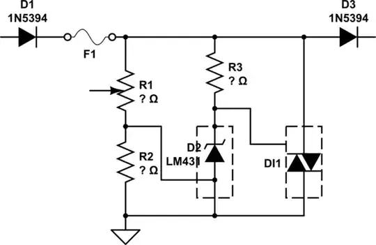
simulate this circuit – Schematic created using CircuitLab
D3 leads to a(n) LM3481 used as a SEPIC (Pg 26) to output 7V for a load that draws between 500mA to 1A (1.25A to be on the safe side).
This leaves me with a number of questions, assuming I want the crowbar to reject (short out) input voltage higher than 35V:
- If the input voltage at D1 is higher than 35V (unlikely, but possibly as high as 40V), will the LM431 become damaged or will the fuse burn out first?
- Will a polyfuse/PTC work for F1? What part type/specifications should I look for?
- To what should I connect the wiper for R1, GND? Does R1 need to be a POT or can I use a fixed resistor?
- What are the values for R1, R2 and R3?
- DI1 is a TRIAC. What specifications should I look for?
- Does the 150mA mentioned in the data sheet have anything to do with the load after D3? What is it actually telling me?
- I know that I can use
Vout ~= (1 + R1/R2)Vrefto work out what R1 and R2 should be, but I don't know how I work outVref. Is thatVinfrom D1 or from the LM431?
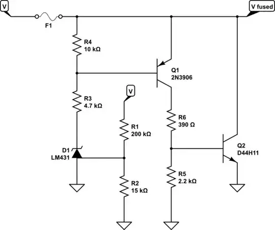
I have seen this as a proposed solution, but apparently the MOSFET doesn't short to ground (according to one of the comments).