Given your desire for as low power as possible, and my realization that this common problem is seldom approached this way. I came up with a self-oscillating switching solution just for the fun of it.
As with any switcher, single-tone emissions/ripple have to be considered (around 20kHz with these values). But if there is any significant ground current, I doubt you can be much more efficient (a more formal switcher with a separate oscillator can be made more efficient and could use a single inductor, but it would require more parts).
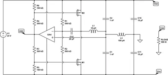
simulate this circuit – Schematic created using CircuitLab
It is basically a relaxation oscillator that modulates the average current through L1 so that it oscillates around the required ground current. M1 and M2 are switched on and off relatively quickly (some acceleration capacitors would help with efficiency) and C12 provides positive feedback so that the opamp/comparator saturates on crossing the threshold (otherwise the load would damp the oscillator and it would become a linear regulator instead).
L3, C10, and C11 are there to filter the ripple and to isolate the oscillation from the load, so as to avoid dampening it too much. C10, and C11 also do double-duty as the regulator input capacitance. Excess energy in L1 and L2 would be returned to the required rail and stored in them. M1 and M2 source-drain diodes are conducting in this design.
R3,R4,R5, and R6 are chosen so as to keep M1 and M2 below threshold when there is no ground current. Unfortunately this also reduces the overall gain of the oscillator loop.
I have not done a very careful analysis of all of the implications of this design (particularly because of it being self-oscillating), so overall stability considerations on load changes might be an issue.
I don't think there are ICs for this type of configuration, which unnecessarily increases the part count and the design constraints. The only ones I know of are the DDR memory termination voltage regulators, but those are intended to work at very low voltages.