Im attempting to make a 8 bit binary calculator that displays on multiple seven segment displays. Can double dabble be done with logic gates. If so, how?
- 168,369
- 17
- 228
- 393
- 43
- 1
- 6
-
You should write more. It's hard for me to know what you really would look back on as a good answer for you from so little writing about what's going on in your mind. – jonk Nov 13 '18 at 17:57
-
There's really no reason to use binary arithmetic in a calculator at all. Calculators from time immemorial have used BCD arithmetic throughout. Since electronics is so much faster than humans are, doing everything 4 bits at a time is not a problem. – Dave Tweed Nov 13 '18 at 18:04
-
I would say you have a two-part question. The double-dabble logic, and then getting the result displayed. I'd go with a microcontroller, send the results to a MAX7219 to drive the display. Then you could also use the display to enter the interim parts of your data entry, + and - signs and what not. The microcontroller will also let you play with added functionality way easier than logic gates that can only do 1 function. But, to each his own ... – CrossRoads Nov 13 '18 at 18:07
-
https://electronics.stackexchange.com/a/441405/124362 – qwr May 28 '20 at 05:09
3 Answers
Any computable function can be implemented with enough logic gates if their implementation permits looping outputs back to inputs to construct flip flops, as most real ones do.
However, the key thing to realize is that because your algorithm of interest is iterative it is stateful rather than combinatorial - it requires memory elements such as registers feeding and fed by the combinational logic gates.
This would generally make implementing it with only logic gates (some in loop connection to create flip-flops) inadvisable; you probably want a mixture of logic gates and compatible-logic-family register ICs.
And more realistically there is no reason other than hobby enjoyment to build this with discrete parts at all. You could for educational purposes build it in a programmable logic device (FPGA, or simply a simulator).
But because it is driving a display, ie, something that operates at only human speed, the usual "needs to be blindingly fast and/or parallel" justification for using dedicated logic rather than a small microcontroller isn't really there. So pretty much any modern, "real problem" implementation would do this in software.
- 33,282
- 3
- 43
- 89
-
(On second thought, it is perhaps possible that you could unroll the iterations into one absurdly long and expensive combinatorial path; it would take more time looking at the algorithm to know for sure. But this would not be sensible, especially if wiring up distinct 74xx series ICs, as you'd need to another copy of the logic to implement each of what is usually an iteration of the same operation) – Chris Stratton Nov 13 '18 at 17:54
-
1Great answer for an overly short and vague question that was difficult to get a bead on. – jonk Nov 13 '18 at 17:55
-
@jonk I personally think their is enough for the answer i wanted. ( I did leave alot to the imagination :) ) ((sorry)) – Karl Streitz Nov 14 '18 at 20:53
For a combinational circuit, jonk's answer about a double dabble algorithm circuit is good.
To summarize, all you need is a special component and a layout that matches the double dabble algorithm.
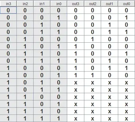
Any 4 bit circuit component that can satisfy the "plus 3 if > 4" property will work. That is, the circuit must satisfy this truth table:
(The x's are "don't care"s, so the circuit can output any value for those)
In disjunctive normal form:
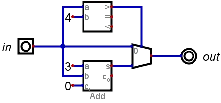
This may be created with an adder, comparator, and multiplexer:
Or you can easily implement the DNF equations. If you're clever you might be able to reuse gates since DNF lists each bit independently.
If you include a bit of logic to detect if a number is > 4 or not and add a multiplexer, the equations for > 4 simplify further.
(Multiple solutions for some output bits)
- 141
- 7
-
1Lovely addition. Definitely a +1. I'll now need to link this in. Hehe. Anyway, thanks so much for your added thoughts. I really like it. – jonk May 28 '20 at 06:30
-
@jonk Thanks. I have had a great time messing around with Digital. In fact, if you google double dabble circuits, a lot of results are from video game communities that are trying to implement binary to BCD circuits within the mechanics of the game. That is in fact my motivation (redstone in minecraft) – qwr May 28 '20 at 06:55
-
I wish stack exchange had a built-in way of sharing Digital (the program) circuits – qwr May 28 '20 at 06:57
-
1I really like Neemann's Digital. Their schematic editor is from CircuitLab and they do provide a place for sharing circuits. It would be very nice if there was a way to add Digital here and also to have Digital include a repository of some kind. But I'm sure that would require some kind of monetization Neemann isn't yet ready for. Meanwhile, there is github and codeshare and I'm sure any number of others for just a "place" for things. But nothing officially sanctioned here. – jonk May 28 '20 at 07:13
-
One suggestion is that you drop the full adder to a half-adder. Neemann's Digital doesn't directly include one (I had to cobble up one of my own.) But it's less logic, by definition. (Obviously, the compare can also be reduced.) – jonk May 28 '20 at 07:14
-
It can be a full adder without carry-in, but the point is simplicity. Since we are always adding a constant we could simplify the logic even more. – qwr May 28 '20 at 07:30
-
Yup. The constants allow still further simplification. You should do all that for us!! – jonk May 28 '20 at 07:31
Necro bump, but I just threw this together while researching binary to BCD this evening. This was the first result on google for this topic, so I figured I'd leave this for anyone else looking.
Edit: I seem to have received a negative score. I hope I have not posted something wrong or perhaps there is some social faux pas I have performed.
-
I did not downvote, but you probably received a downvote for posting a diagram with no explanation at all – qwr Jun 27 '21 at 02:51

