5

I've been looking for a simple LED fade in/fade out circuit when power is turned on/off for a 12 V LED. I have tried the following circuits but the problem is that I can't reach the full brightness of the LED that it reaches when simply connected to 12 V power supply.

I think it is due to the resistor which connects the capacitor to VCC. It allows the capacitor to charge slowly and show fade in effect, but also limits the current and thus max output voltage. I have tried altering the component values but if I decrease the value of the resistor the fade in effect gets faster.

Please help me with this.

EDIT :-

(Sorry for not mentioning these points before).

1) Don't worry about the fade in/ fade out time being same. I just need a good fade in effect and don't care about the fade out.

2) WHAT I NEED IS - I just need a circuit at the output of which the voltage goes from 0 to 12v when power is on and from 12 to 0v when power is off. Please suggest me a new circuit if this is not possible with the one below.

Thanks...

schematic

simulate this circuit – Schematic created using CircuitLab

Electric_90
  • 2,112
  • 13
  • 25
  • 1
    increasing the capacitance will slow the circuit, so do that and reduce the resistor. – Jasen Слава Україні Nov 07 '18 at 09:11
  • 2
    Note that you've typed 22OO instead of 2200 in your third diagram. If you do that in a simulator it may not work. – Transistor Nov 07 '18 at 09:20
  • Since an RC performs an exponential curve and since human eyes are logarithmic in response, these may be good fits for each other -- if and only if you design something that is a voltage-controlled current source/sink for the LED. I don't see any such circuit in the responses so far, though I see plenty of ideas. – jonk Nov 07 '18 at 17:08
  • It is better to place the LED strip between 12 V and collector of Q1, not between emitter and ground. – Uwe Nov 08 '18 at 15:19

6 Answers6

2

Firstly the warning: -

the problem is that I can't reach the full brightness of the led that it reaches when simply connected to 12v power supply

Don't connect a standard LED directly to a voltage supply unless you want to risk breaking it - always use a current limiting resistor.

Back to your schematic; you are using an emitter follower to drive several series LEDs and this naturally loses about 0.7 volts between input (base) and output (emitter) and this might explain some loss of brightness. To restore the current, try lowering the resistor in series with the LED string but heed the warning about it being a current limiting resistor and don't make it so low that you damage the LEDs.

You are also using a potential divider to drive the base and this naturally reduces the base voltage and, in turn, this naturally reduces the emitter voltage. I would move R2 to the left of R1 and make it lower in value than R1. For instance, if R1 is 10 kohm then the newly positioned R2 should be about 1 kohm.

Andy aka
  • 434,556
  • 28
  • 351
  • 777
  • Why would you make R2 less, wouldn't that affect the discharge rate? If R1 and R2 were identical I could understand. However if R1 and R2 are not identical then wouldn't R2 be \$R2_{new} = R2_{original}-R1\$. Not a critique btw, a genuine question –  Nov 07 '18 at 09:51
  • @Doodle when R2 moves to the new improved position you want its value to be a fraction of R1 so that charge and discharge rates are about the same. – Andy aka Nov 07 '18 at 09:53
  • But doesn't the discharge resistance go from being just R2 to R1 + R2? If R1 for example was already 1k and R2 was 10k. Then wouldn't moving R2 and making it smaller than R1 affect that discharge rate? As the discharge resistance would go from 10k to 1.1k for example. –  Nov 07 '18 at 09:56
  • @Doodle R2 needs to move right? You OK so far? It has to create a new discharge path without forming a potential divider right? So you put it where I said but, with its original value, the discharge time becomes double the charge time right? Are you with this and do you see where I'm going with this? – Andy aka Nov 07 '18 at 10:01
  • I do understand and I can completely see this in the example where R1 and R2 are the same. But like I said, if R1 and R2 are not identical in the case you don't want a symmetric charge/discharge for example. Does this still hold true? –  Nov 07 '18 at 10:14
  • You have to use appropriately scaled resistors and, if the discharge is meant to be faster than the charge time then you use a diode across R1. If you don't understand this, please raise a formal question. – Andy aka Nov 07 '18 at 11:46
  • Thanks for your answer. Changing the position of R2 isn't helping, it is just generating excessive heat on R2 as it is directly connected from vcc to gnd. – Electric_90 Nov 08 '18 at 10:31
  • @Andyaka, please see my edits in the post. Also, don't worry about the led being blowing up as the output load is capable of taking 12v. Ignore the resistor in series with led in circuit 1, I removed it and brightness is still low. – Electric_90 Nov 08 '18 at 11:00
  • Show one circuit in your question that most resembles the circuit you have tried with the emitter follower. Don't post alternative untried circuits as these just confuse the question and lead to doubts. Anyone answering won't need examples of circuits. Be specific about the load and what current you want. Be clear about the power supply voltage and variations that it may be subject to. – Andy aka Nov 08 '18 at 12:30
  • I've tried all the circuits mentioned including the one you suggest but they didn't work. As I said in the edited post, Input = 12v/500ma, Output = 0 to 12v and 12 to 0v when power on/off, the current taken by load at peak brightness is 200ma. – Electric_90 Nov 08 '18 at 12:53
2

schematic

simulate this circuit – Schematic created using CircuitLab

With this circuit, there is a voltage divider circuit going on with R1 and R2 which means at the base of your transistor you're only seeing a ratio of your input voltage.
\$V_{BASE} = (R_{2}/(R_{1}+R_{2}))/V_{IN}\$

This means that your base voltage is going to be less than that of your collector voltage depending on what values you use for R1 and R2, this means that your transistor won't fully saturate which means there will be a larger voltage drop across your transistor (\$V_{CE}\$)

Even in the best case scenario you're going to lose ~0.7V across your transistor even when fully saturated. You're thinking your LED is still connected to 12V when the reality is that after the transistor it's more like connecting the LED to ~10-11V (depending on your values for R1 and R2)

Then using Ohm's law it's simple to see why your LED isn't getting as bright, less voltage with the same resistance = less current.
What you need to do is calculate what the voltage drop of your transistor will be and then figure out a new value for you current limiting resistor based on your new voltage (\$V_{IN}-V_{CE}\$)

Electric_90
  • 2,112
  • 13
  • 25
  • Thanks for your answer, I checked the output voltage of the circuit and it is as you are saying 9-10V. But the problem is that on altering the resistor values the led fade in time changes. (i.e. if I decrease R1 the brightness of led increases but fade in time of led decreases which I don't want). – Electric_90 Nov 08 '18 at 09:43
  • please see my edits in the post. – Electric_90 Nov 08 '18 at 11:01
  • @Electric_90 What I'm suggesting is to leave R1 and R2 as they are and just change the value of R3. If R3 is 330Ohm with 12V for example, you might want to change R3 to 270Ohm if you have 10V. Current will be the same in both cases therefore LED brightness is the same. An LED is a current controlled device remember –  Nov 08 '18 at 13:10
  • Yes you are right but since the led is not the normal 3v and rather is a 12v one, even removing R3 all together won't work. Is there anyway to step up voltage at output to the same 12v as input ? – Electric_90 Nov 08 '18 at 13:16
  • 1
    @Electric_90 with a transistor, even in the best case scenario you're going to lose at least 0.7V, there's no way around that using just a transistor whilst keeping the fade in/out functionality –  Nov 08 '18 at 13:28
  • Also can you post a datasheet to your LED or at least a part number –  Nov 08 '18 at 13:29
  • I am sorry, I didn't mention the type of led, its actually a led strip. Is there any other way to accomplish the fade effect without the use of a mcu. – Electric_90 Nov 08 '18 at 13:32
  • Ah ok, so the problem is that the LEDs are already integrated onto the strip and you can't change them. I understand. Unfortunately almost all discrete fade in/out circuits utilise a transistor in some way or another. –  Nov 08 '18 at 13:36
  • Let us [continue this discussion in chat](https://chat.stackexchange.com/rooms/85525/discussion-between-electric-90-and-doodle). – Electric_90 Nov 09 '18 at 03:25
2

LED irradiance is a function of current, roughly speaking. LED illuminance is more like a logarithmic function of irradiance. So to achieve a roughly "linear" increase or decrease in perceived brightness, you will want the current in the LEDs to follow a rough approximation of the RC charging curve (which is exponential.) Unfortunately, just driving LEDs using an exponentially changing voltage doesn't do the trick. You may prefer to control the LED current as a function of the charging voltage.

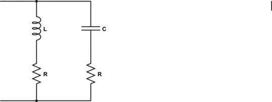
The following circuit will achieve this to a reasonable approximation:

schematic

simulate this circuit – Schematic created using CircuitLab

The current mirror formed from \$Q_2\$ and \$Q_3\$ will operate reasonably well down into shallow saturation for \$Q_3\$. This means you can almost achieve the entire \$V_\text{CC}\$ voltage across your LEDs, less perhaps half a volt or so. And they will control the LED current the entire time, as well.

\$Q_1\$ is working as an emitter follower. As the capacitor voltage rises, so also does the emitter -- in relatively close lock-step. This means that the voltage on \$C_1\$ sets the current in \$R_\text{SET}\$, as the collector of \$Q_2\$ will always be only about a diode drop above ground.

The only trick in all this is that \$Q_1\$ requires a base recombination current to operate. This "drags" on the rising rate of \$C_1\$'s voltage and, likewise, accelerates the falling rate. However, this circuit uses only \$R_2\$ for charging but the sum of \$R_2+R_3\$ for discharging. The larger value of \$R_2+R_3\$ (which would otherwise appear to require a longer discharge time) is compensated by the recombination base current for \$Q_1\$, which also discharges \$C_1\$. So with a little bit of adjusting the ratio of these two resistors you can get approximately equal rise and fall times for the currents in the LEDs.

$$R_\text{SET}=\frac{V_\text{CC}-\frac{I_\text{LED}\cdot R_2}{\beta}-1.5\:\text{V}}{I_\text{LED}}$$

If you are using a \$12\:\text{V}\$ supply and want a peak of about \$20\:\text{mA}\$ in the LEDs, then using the above circuit you'd get something like \$R_\text{SET}\approx 390\:\Omega\$ (assuming \$Q_1\$'s \$\beta\approx 240\$.) Of course, it might be less than that too but this gets a ballpark resistor value to start with, regardless. (With only \$5\:\text{V}\$, \$R_\text{SET}\approx 39\:\Omega\$.)

Anyway, it's easy to try it out. So long as the LED current is modest (in the vicinity of \$20\:\text{mA}\$ or less) the dissipation in the three transistors should be within spec without the need for heat sinks. \$R_\text{SET}\$ should be at least \$\frac14\:\text{W}\$, though. Be sure to verify what I'm saying, by testing and feeling the change in temperature of all three BJTs and \$R_\text{SET}\$, though. Always verify and make adjustments where you feel better is needed.

jonk
  • 77,059
  • 6
  • 73
  • 185
  • Thanks for your answer. Please see the edits in my post, Can I replace 2N3904 with BC548 ? – Electric_90 Nov 08 '18 at 11:23
  • @Electric_90 There is nothing particularly critical about the design. These are LEDs, not scientific instrumentation. Even the current mirror pair won't be perfect in reflecting the current accurately. But this isn't rocket science. The approach will get you close. And that's all you need. Worse, fixes to improve the accuracy would cost voltage overhead. And you've already complained about losing too much of that. So I think you'll be okay here. – jonk Nov 08 '18 at 13:06
1

schematic

simulate this circuit – Schematic created using CircuitLab

Figure 1. Move R2 to position shown.

You can avoid the potential divider effect of your first circuit by moving R2 to the switch. It will then have no effect when SW1 is on but will provide a discharge path when SW1 is off. Its value could be about 1/10 that of R1 to keep the charge and discharge currents similar.

Transistor
  • 168,990
  • 12
  • 186
  • 385
0

Taking a look at your second circuit...

Simulation

As you can see on the traces in the image above, Q1 is never getting enough voltage to fully turn on. The red trace is at the switch, the green is in the centre of the resistor divider and the blue is at the base of the transistor. This simulation is with the switch being held on for 2s and then let go for 3s.

Your resistors are too high value (and are in an unnecessarily complicated network). I'd try reducing the value of your resistors. The capacitor charge speed will be controlled using the capacitor time constant equations, make sure you've taken a look and plugged the numbers you want into there. A larger capacitor will take longer to fully charge(with resistance being constant).

BenAdamson
  • 588
  • 5
  • 15
0

Instead of using RC you could go PWM. Modern cars use PWM circuits to dim or fade interior and instrument lights. I have seen interior dome lights that fade up and fade down, theater style.

John Canon
  • 526
  • 2
  • 8
  • You would need some sort of micro that is capable of PWM, not to mention you'll still need a transistor so OP is still gonna have at least 0.7V drop –  Nov 15 '18 at 09:05