1

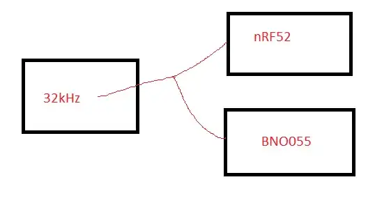
Is it possible to share 32.768kHz crystal for nRF52 and BNO055? The purpose is reducing cost&space.

enter image description here

enter image description here

Preferred crystal this one: FC-135R https://support.epson.biz/td/api/doc_check.php?dl=brief_FC-135R&lang=en

enter image description here

Also,how can i handle different load capacitance values?(If sharing possible,surely) Other question's accepted answer not satisfy me

Berker Işık
  • 445
  • 2
  • 14
  • 2
    Already answered. Google hit if you searched for "share crystal between two microprocessors". https://electronics.stackexchange.com/questions/15407/whats-the-schematic-to-share-one-crystal-with-two-micros – scorpdaddy Nov 06 '18 at 14:13
  • Doing this for the low frequency crystal may be a little different - are you sure you need it at all? or for both? Both parts can be operated without a crystal, so the question is if your application demands that they have one. If you do need to share it you may need a buffer amp or to figure out details of the oscillator circuits. Another idea could be to feed a divided clock from the MCU to the sensor. – Chris Stratton Nov 06 '18 at 14:20
  • Both parts could be work using internal RC oscillator. This's true. But ppm values are high also for best performance(bno055) and low power(nRF) consideration,the external ones recommended by manufacturers. – Berker Işık Nov 06 '18 at 15:41
  • Why specifically do you *care* if the frequencies are accurate? "Best performance" is the kind of term used by someone who hasn't actually thought about the actual needs. – Chris Stratton Nov 06 '18 at 15:56
  • Differences between internal and external crsytals actually didn't tested. This term is quotation from datasheet.In page100 stated that "To get the best performance out of BNO055, it is recommended to use the external crystal". That's just try to consider recommendations. – Berker Işık Nov 06 '18 at 17:58

2 Answers2

0

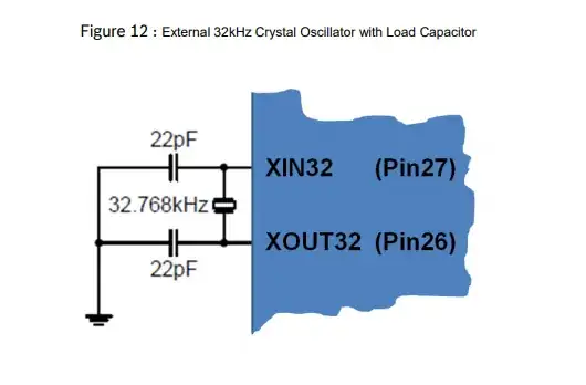
Sharing can be done if you design with care. Looking at your two devices I would place the 32.768KHz crystal very close to the BNO055 device. That chip would utilize its internal oscillator between the XIN32 and XOUT32 pins to make the actual crystal oscillate.

From the BNO055's XOUT32 pin you would just route a single conductor to the nRF52 device. You will have to look closely at the nRF52's data sheet to see which one of the XL1 and XL2 pins is the oscillator input pin. It is the input side that you want to connect the signal from the BNO055's XOUT32 pin. You will leave the output side of the nRF52's oscillator open circuit.

Another important consideration is that the nRF52's oscillator input and the connecting trace will add some picofarads of capacitance to the crystal oscillator so you would ideally need to reduce the crystal matching capacitance on the BNO055's XOUT32 pin by an equivalent amount that was added by the nRF52's input.

If either of these chips is powered off separately from the other it may cause problems with the coupled oscillators so make sure you prototype the proposed circuit and power cycle the one component that goes off to make sure there is no disturbance to the other device.
Michael Karas
  • 56,889
  • 3
  • 70
  • 138
  • Yes, nRF has another input for 32MHz crystal. 32kHz is "low-frequency XO input". 2 capacitors should be adjusted according to "trace"+"pin"+"crystal" capacitances. There's is a example here: https://devzone.nordicsemi.com/b/blog/posts/general-pcb-design-guidelines-for-nrf52 – Berker Işık Nov 06 '18 at 16:05
0

Simply connecting output of the inverter to the inputs of other chip's inverters might fail as some (not all) chip 32.768kHz oscillators might contain built-in capacitance (or part of it), the result being the crystal loaded non-uniformly and unpredictably.

That might cause unreliable starting and extra frequency deviation.

Another problem is that when your wire between chips that carry 32.768 kHz signal gets long, it might catch more noise and thus make oscillations unreliable again.

The possible ways to solve:

  1. Put buffer IC close to the only chip selected to oscillate with the crystal. Account for the input capacitance of such buffer (~5pF per pin). Take care not to get buffer ring over the extremely slow-slew-rated, sinusoidal output of the oscillator. You can use slow inverter like CD4069 or Schmitt trigger like 74HC14.

  2. Make your own oscillator using unbuffered CMOS inverter like 74HCU04 (note the U letter!) or CD4069 (see https://i.stack.imgur.com/m8cPz.png). Then buffer the signal on the remaining inverters: 1 common buffer and then individual buffer per every of your consumer chips.

lvd
  • 290
  • 2
  • 10
  • It is not preferred one extra IC instead of second crystal. If need,maybe putting second crystal more easy. – Berker Işık Nov 06 '18 at 16:12
  • It is not obvious from your question. – lvd Nov 06 '18 at 16:16
  • Also the logic gates could be as small as this one: https://assets.nexperia.com/documents/data-sheet/74HC_HCT1G14.pdf (sot353, 2.1mm X 1.2mm). – lvd Nov 06 '18 at 16:24
  • Crystals so small too. I stated in the question "The purpose is reducing cost&space". But maybe this not enough clear,sure. – Berker Işık Nov 06 '18 at 18:15