2

What is the main reason some micro-controllers form a push-pull topology when set as an output pin?

enter image description here

My only guess is not to load the pin. But I couldn't find enough information about the reasons. What are the benefits of push pull output here?

user1245
  • 3,955
  • 4
  • 37
  • 87
  • 3
    If not push-pull, what would you expect to see the pin configured as when it's an output? – brhans Oct 30 '18 at 16:19
  • The answer from Abisheck in https://electronics.stackexchange.com/questions/28091/push-pull-open-drain-pull-up-pull-down might help. – Michel Keijzers Oct 30 '18 at 16:19
  • When I use a comparator, or a schmitt trigger do they have push pull as well internally before their output? Is this used for all ON OFF outputs? – user1245 Oct 30 '18 at 16:21
  • That answer says *"When the output goes low, it is actively "pulled" to ground." I think it must say "When the input goes low, the output is actively "pulled" to ground. " Something is wrong articulated in that answer. – user1245 Oct 30 '18 at 16:26
  • @atomant try reading it as "When the output *is supposed to go low*, it is actively pulled to ground by the lower transistor" – Chris Stratton Oct 30 '18 at 17:01
  • Your question is wrong. You do not *"set it as output"*, but *"you enable the push-pull mode"*. Pins can have lots of features. What do you want answered? – Jeroen3 Oct 30 '18 at 18:31

3 Answers3

3

Push-pull means you can drive the output line high (by connecting it to VDD) or low (by connecting it to ground). A proper output needs to be able to do both of those things. [1]

If you're asking why the schematic shows transistors, that's a different question. The transistors form a CMOS inverter. They work exactly the same way as the triangle with a dot on the front. They're probably drawn separately because the transistors that drive the output pin are larger and can supply more current than the transistors used for internal logic. The two inverters together form the output buffer for the pin.

[1] You can also have an "open-drain" output that only has the pull-down transistor. You would then connect a pull-up resistor to the pin. The advantage of this is that you can make a "wired-OR" circuit where multiple open-drain outputs control the same line. The disadvantages are that the output's rise time is slower and the circuit uses extra power when the output is low.

Adam Haun
  • 21,331
  • 4
  • 50
  • 91
  • Some comparators have open collector output? Which one of your examples do they fit? – user1245 Oct 30 '18 at 16:39
  • 1
    Open collector is the bipolar transistor equivalent to open drain in MOS, that was mentioned above – Chris Stratton Oct 30 '18 at 16:47
  • 1
    @atomant open collector and open drain only differ in the type of transistor used. They are roughly the same outside the IC – jaskij Oct 30 '18 at 16:48
  • 1
    As Chris and Jan said. "Open-collector" is sometimes used as a generic term, but in CMOS ICs it's always really open-drain. – Adam Haun Oct 30 '18 at 17:08
0

microcontrollers get used in all kind of weird places and putting in the extra transistors to enable push/pull is often worth it to enable those uses.

Push/Pull along with a high-impedance state can combine to mimic either open drain or common collector making it flexible in that way.

Push/pull are not dependent on external resistors to pull the output high or low. This means less external components that need planning for, faster switching and lower power consumption when not switching.

ratchet freak
  • 2,803
  • 14
  • 12
  • I don’t understand but so why is that used? What happens if it is not used? A power supply can also be turned on or off but it doesnt have push pull output. Is this only for digital outputs? – user1245 Oct 30 '18 at 16:32
  • The depicted part of the output is basically the same regardless if one or both of the drivers can be disabled or not. – Chris Stratton Oct 30 '18 at 16:45
0

From the comments under ratchet freak's answer:

A power supply can also be turned on or off but it doesnt have push pull output.

That is correct but a power-supply can only source current. It cannot sink current. For flexibility the micro-controller can do both.

schematic

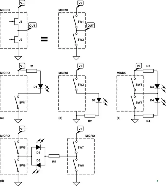
simulate this circuit – Schematic created using CircuitLab

Figure 1. The equivalent diagram (top) and various options available with a push-pull output.

Having a push-pull output gives great flexibility in driving various loads.

  • (a) A low-side switch can handle a load connected to positive supply.
  • (b) A high-side switch can handle a load connected to ground.
  • (c) A push-pull arrangement can switch both. When SW3 (high side) is closed D4 lights and when SW4 (low side) is closed D3 lights.
  • (d) More complex arrangements are available such as this H-bridge arrangement which could drive, for example, a bi-coloured, 2-pin LED. To turn on D5 close SW5 and SW8. To turn on D6 close SW6 and SW7.
Transistor
  • 168,990
  • 12
  • 186
  • 385
  • Thank you for examples. Is (a) for when the pin is set for input. For analog or digital inputs? – user1245 Oct 31 '18 at 00:15
  • No, all of the examples are digital outputs. They are either on or off. You wouldn't connect an LED to an input. Read the answer again. – Transistor Oct 31 '18 at 00:28
  • Can you also add how input looks like to your answer? It would be a great reference- – user1245 Oct 31 '18 at 02:10
  • No, I think that would be not relevant to your original question. I think you should ask a separate question for that. It occurs to me that it may not be clear from my answer that the switches inside the 'micro' boxes in Figure 1 represent the FETs in your push-pull output diagram in the question. Did you understand that? – Transistor Oct 31 '18 at 07:15