3

In a previous question about using MOSFETs in parallel to increase current for DC operation in the linear region, it was pointed out that MOSFETs do not like to be used this way.

I thought of a way to avoid using the MOSFET in DC in the linear region (with the thermal problems) but still get DC at the output.

Could I use two sets of MOSFETs in parallel and activate one set for a time, then the other set, then the first set, and so on? I would use two Vin voltages with a Pi phase shift. Would that work? I'd calculate the switching frequency later.

Dual Mosfet

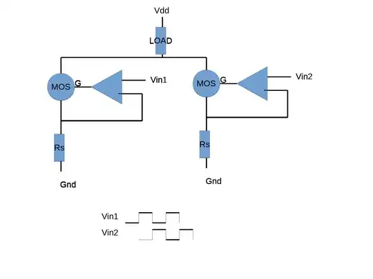
The image shows two MOS but I could have 4 on each side to allow more amps.

I am very new to electronics, please tell me if it's stupid or if it may work. I do not have much requirement on the stability of the output. I just want to push some adjustable current to test that a fuse blows at the right current.

flaviut
  • 386
  • 3
  • 18
Akira Doe
  • 137
  • 1
  • 7
  • 1
    What do you mean by "avoid using the MOSFET in DC"? Should you say "... in linear region"? – Long Pham Oct 26 '18 at 15:33
  • No, I mean DC. I was told that when you try to use MOSFET in DC like in the link I posted in the first message, there is a danger of thermal runaway. If Vin is at a constant value in time, for a high current load, part of the MOSFET (which is made of many small mosfet cells) will heat up, get more current, heat up ... and blow. I am just repeating what I was told, my knowledge do not extend that far. But when looking at the SOA of the MOSFET datasheet, I can read that it can work in higher current (Id) when not used with DC Gate voltage. – Akira Doe Oct 26 '18 at 15:58
  • 1
    @AkiraDoe No, you mean "DC _in the linear region_". MOSFETs are happily used all the time to switch DC, but then the MOSFET is either fully saturated or fully depleted, only spending a short time in its linear region during switching. Your situation is different not because you're using DC, but because you're permanently in the FETs linear region. The answer you refer to is actually pretty clear on this... – marcelm Oct 26 '18 at 16:03
  • @marcelm : Thank you for your explanation. Indeed, I misunderstood the question from LongPham. – Akira Doe Oct 26 '18 at 16:12

1 Answers1

1

All your circuit achieves is a reduction of the time spent for each MOSFET in its linear region. In fact, you could use both circuits in parallel fed from a common input voltage that is half the voltage necessary to produce the same current (should only one circuit/one MOSFET be used).

This has the effect of properly sharing the current equally between MOSFETs but it doesn't totally mitigate against thermal runaway (due to conduction in the linear region of a MOSFET); it just halves the problem. However, it is streets ahead of just paralleling MOSFETs and hoping for the best.

Andy aka
  • 434,556
  • 28
  • 351
  • 777
  • I am very grateful that you take patiently the time to explain me things that must be pretty obvious to you. In proposing the above circuit, I thought that the varying operation point would decrease the thermal load on the MOSFET and limit the risk of thermal runaway. I guess I have no other option than to parallel ten ou more (MOS+OPAMP) and use a very large heatsink ... I have found some special FETs designed to work in the linear region (with internal architecture to avoid thermal runaway) but they are 30euros apiece !! I will stick to cheaper ones like the BUK7575-100A to try. – Akira Doe Oct 27 '18 at 12:10