2

What kind of self-test circuits or method do they used in the GFCI outlets generally? Is it just firmware or is there a physical addition (and what it is usually?)

This is because after 2015, it is required by UL. But there were many old stocks without it and the physical appearance of the product is the same. So is there any way to recognize or test the function if I buy a product which both has the function and not (depending on whether manufactured after or before 2015 which they don't specify?)

Note: This isn't about the manual test button, but a circuit inside... see

New Self-Test Requirements:

n Underwriters Laboratories (UL) made new revisions to the UL 943 (GFCI) standard that will take effect on June 29th, 2015.

n UL REVISION 943 STATES:

  1. All GFCI receptacles must have an auto-monitoring (self-testing) feature.
  2. If auto-monitoring determines the GFCI can no longer offer protection, one or more of the following will happen:
    (1) Unit is no longer able to reset and denies power.
    (2) Unit can reset and is subject to the next auto-monitoring test cycle within 5 seconds of power to the device.
    (3) All GFCIs must provide audible or visual indication if it does NOT go into power denial.
  3. Provisions to ensure receptacle will not reset if miswired during installation as well as reinstallation. "
Nick Alexeev
  • 37,739
  • 17
  • 97
  • 230
Samzun
  • 123
  • 1
  • 8

2 Answers2

3

What kind of self-test circuits or method do they used in the GFCI outlets generally?

An temporary imbalance (leak) between the hot and neutral is created, and the GFCI circuit should detect it.

Is it just firmware or is there a physical addition.

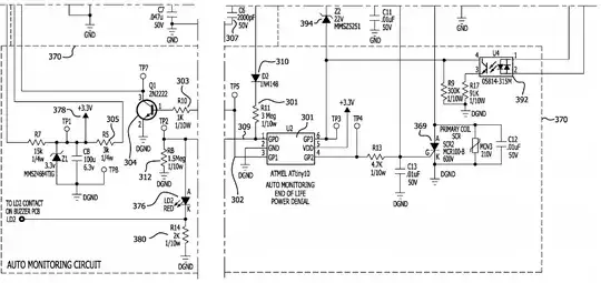
There is a physical addition: a resistor for creating a leak, some kind of switch for connecting and disconnecting this resistor. (By the way, most GFCI deices are hard-wired, and they don't have microcontrollers with firmware.)

I've designed an GFCI (RCD) circuit once, and it has a self-test. R9 provides the controlled leakage. U2 is the solid state relay for connecting the R9 during self-test and disconnecting it the rest of the time.

GFCI RCD circuit with self test

Nick Alexeev
  • 37,739
  • 17
  • 97
  • 230
0

The automatic selftest is something I had to do some digging on.
I found patent US20170299656A1, which includes a schematic and detailed explanatory text.

enter image description here

It looks like it works just as the test switch, except the current stays lower than the trip threshold and it measures the feedback of the coil. It only self-tests the sensing part of the GFCI. Not the breaker part.

One advantage I can see in this is that if you have a DC (fault) current that saturates the sensing coil, this condition will be detected. A DC saturated coil significantly inreases the trip threshold or completely inhibits the device.

Jeroen3
  • 21,976
  • 36
  • 73
  • I was not referring to the Test button.. but self-test in which the GFCI would automatically test itself every minute automatically. – Samzun Oct 22 '18 at 06:26
  • 2
    see the added passage above in UL943 which quoted: "New Self-Test Requirements: n Underwriters Laboratories (UL) made new revisions to the UL 943 (GFCI) standard that will take effect on June 29th, 2015. n UL REVISION 943 STATES: 1. All GFCI receptacles must have an auto-monitoring (self-testing) feature." – Samzun Oct 22 '18 at 06:48
  • 1
    @Samzun Automatic mode... That was not clear. I have no clue how a breaker can test itself without actaully testing the breaker part. This UL seems to make it less safe, with the lockout (people will bypass them) and probably periodic inoperability due to test. – Jeroen3 Oct 22 '18 at 07:10
  • I saw this discussion in 2012.. https://www.diychatroom.com/f18/leviton-self-test-gfci-questions-139980/ that was 3 years before it becomes mandatory.. so I need to see some circuit diagram of it.. or circuit diagram of GFCI in general and how this automatic self test circuit is added or adapted. – Samzun Oct 22 '18 at 07:25
  • @Samzun I've changed my answer to the correct self-test type. – Jeroen3 Oct 22 '18 at 13:29
  • Thanks. So there is really circuit addition. A local distributor just put sticker to the box "includes automatic self-test" to compete with others.. but the technical told me they couldn't see any difference in the circuit compared to older stock without it and they just had to trust the maker in china.. so there is a difference. Does anyone have actual picture of the inside of a GFCI outlet. And to to be sure, I wonder what is the most sophisticated brand that has 240v too? Anyone knows? – Samzun Oct 22 '18 at 13:44
  • if a GFCI is advertized for 120V. do you think it can be used for 240V? Are the circuits voltage specific? The Hubbell GFCI (where you showed the schematic and hence at least not a fake) seems to come only in 125v and in Europe web site, Amazon doesn't seem to sell GFCI much. What countries don't use GFCI? Doesn't Europe use them? – Samzun Oct 22 '18 at 22:06
  • Technically a GFCI detects only difference in current. A 240V outlet would have smaller current.. so can we say all 120V GFCI outlets can work for 240V source? – Samzun Oct 22 '18 at 22:31
  • 1
    @Samzun The power supply of the electronics might not like 240V. Europe does use GFCI, they are called RCD here. They are in the distribution box, not the socket. – Jeroen3 Oct 23 '18 at 05:35
  • There are available GFCI 2 pole breakers. There are 2 hot wires and one neutral. Why is there a neutral when you are supposed to connect them hot to hot line producing 240v? unless it can also produce 120v from line to neutral? Then how does the current comparator works? Can it shift from hot to hot and hot to neutral?? – Samzun Oct 23 '18 at 06:13
  • Let us [continue this discussion in chat](https://chat.stackexchange.com/rooms/84813/discussion-between-jeroen3-and-samzun). – Jeroen3 Oct 23 '18 at 06:56