3

I bought a car reversing sensor system... I bench tested it with a simple 12 V PSU, and it works great. Integrating it into my car is another matter since finding out that most cars since 2008 have CAN bus wiring. So a simple piggy back into the reversing light 12 V + is fraught with problems (apparently, reading up on this and googling many pages)

There is a whole line of 'expensive' addons that get you into the CAN bus network without upsetting the system, but they are more expensive than the reversing sensor kit!

I don't want to piggy back into the wiring then, but can I use some kind of voltage sensor taped to the reversing light's insulated wiring and get a signal to switch a relay to supply a 'direct from the battery' 12 V to the kit I bought?

I had thought of an optical circuit (when the reversing light comes on) to detect that, but would have to be sensitive to bright light only (the bulb) rather than false trigger by daylight.

Hmmm.. I am open to any ideas, the simpler the better.

Peter Mortensen
  • 1,676
  • 3
  • 17
  • 23
Alan
  • 31
  • 1
  • 2
  • Are you only looking for a 12volt source? If so, that's part of the CANBUS connector and it's multidrop, so you can hook in by splicing the cable and/or-not adding two a y-connector scheme. Also if can nad don't mind wiring back to the ODB diagnostic connector that's another option. – kenny Sep 13 '12 at 14:50
  • This is very interesting and I need soem more information, please. – Alan Sep 14 '12 at 06:56
  • On which aspect here's info on ODB-II http://www.obdii.com/connector.html – kenny Sep 14 '12 at 10:58
  • Hi Kenny.. I'm getting used to thereply method of the forum now.. didn't notice your reply at frost.. sorry..thanks for the diag and your trouble. :) It's a little over my head though.. except to actually look for this connector and ascertain that my VW Polo (2006) really does have a CANBUS network.. From your first comment though, can i actually hook my 12v + lead into the wiring behind the bulb, then, and just ground the 12v - without upsetting the 'network'? Boy would that make my life easier! – Alan Sep 14 '12 at 16:12
  • Hi **Kenny** Can anyone else confirm you can 'just' splice into the 12v + in the wiring loom behind the reversing light bulb to get the 12v positive i need to run the reversing sensor kit i bought and not upset the CANBUS system? – Alan Sep 20 '12 at 15:32
  • Hey Alan if you put an @ sign in front of the name (e.g @kenny), the person will get 'notified'. Almost any reasonably modern car has CANBUS. I don't know about a particular light bulb, but probably everything is 12v in a car. – kenny Sep 20 '12 at 15:52
  • Thanks for the heads up on the forum notification method and your help of course. @Kenny :) I just need to find which wire out of the loom is which, now.. – Alan Sep 21 '12 at 16:09

2 Answers2

2

Instead of a relay, I would use an optocoupler with a resistor in series. The relay will be an inductive load, which the circuit that drives the backup light might not be designed to handle.

On the output side of the optocoupler you have a collector and emitter of a transistor that is either on or off. This won't be enough to switch the power to your sensor directly, but it can switch something else that can. Two simple solutions for that would be a P channel FET or a PNP transistor. Both would be a high side switch.

For the FET, there would be a pullup on the gate to the source, with the optocoupler pulling it low. Plenty of FETs can take 12 V on the gate, but unfortunately it's not that simple. In a car, there can be significant voltage spikes. Getting a FET rated for 60 V is no problem, but you're not going to find one that will allow -60 V on the gate. One way to fix this is to use a zener diode to limit the gate voltage. That requires an extra resistor in series with the optocoupler output so that the zener has something to work against.

Given all the gate drive problems of a P FET, the PNP solution will be simpler:

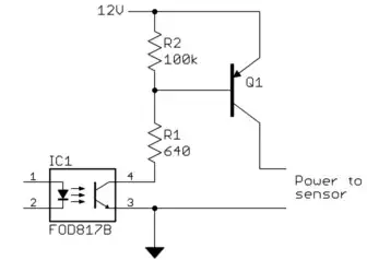
When the LED in the optocoupler is on, the output transistor goes on. This brings the bottom end of R1 to nearly ground, and provides about 20 mA base drive to Q1. This times the gain of Q1 is the amount of current it can switch on to power the sensor. For example, if the gain of Q1 is 40, then it can provide up to 800 mA. You want to leave some margin, so that would be good if the sensor is rated for 500 mA.

When voltage spikes happen, the voltage at the base of Q1 goes up. The combination of R1 and the optocoupler output transistor will have this higher voltage accross it. The current will increase, and eventually the optocoupler transistor may not be able to support the higher current, so the voltage across it increases. This increases its dissipation momentarily, but for short spikes this is no issue. It is easy to find optocouplers that can support 25 mA output current or more. The real issue to surviving spikes is to make sure that both the optocoupler output transistor and Q1 are rated for the higher voltage. 60 V should do it for Q1, and the optocoupler output actually gets a little less voltage stress, but these are not hard specs to meet. Some flavor of the cheap and plentiful FOD817 for the optocoupler should do it, for example.

Peter Mortensen
  • 1,676
  • 3
  • 17
  • 23
Olin Lathrop
  • 310,974
  • 36
  • 428
  • 915
0

I don't see the problem. The reversing light may be CAN-controlled, the bulb (or LEDs) itself isn't, so you should be able to tap its switched 12 V on the socket.

Alternatively you could tap into the CAN bus and listen for commands to switch on or off the reversing light, but then of course you would have to know the command which does this. In any case, I would only listen, and never send any data myself onto the bus. The car's computers' software has been thoroughly tested, but they may not cover every kind of tampering, and if the software goes haywire anything can happen, including injuries.

stevenvh
  • 145,145
  • 21
  • 455
  • 667
  • What if the lights are LEDs on a circuit board, where is 12v to the bulb? "Just" listening for CAN packets is hardly a trivial exercise... – Tim Nov 13 '14 at 16:16