I have a barcode scanner working on 433Mhz (FSK). Since this is a relatively old product and the PC software is not working with Windows 10's and I can't use the SDK anymore. I, therefore, have decided to make my own receiver hardware and a PC software accordingly.
I have disassembled the scanner and directly wired to a simple logic analyzer from the device's transceiver module. There is not much information about this module. But, I know pin-outs, their functions and "receives and transmit data packets at 36864 baud Manchester encoded".
So, I have opened the old program with an old Windows OS version and start scanning right after I clicked the start button on the Logic analyzer. Normally, the receiver has continuous reception regardless if I am using the scanner or not. We can consider this as other emissions in the environment.
As far as I discovered, there is a carrier detect signal leading the scan data and around this (beginning of the carrier detector after carrier detect signal) there are serial of bits looking like preamble with 0's (if I am not mistaken, because shouldn't that preamble always right after the carrier signal as part of the data?)
Logic analyzer Manchester setup:
And some output from the analyzer (you can ask more detailed look if you like):
There are two consecutive barcode scannings here.
I have tried several version of the settings. I tried to place some random numbers in the Preamble bits field or different bit rates, positive or negative edge, LSB or MSB but I couldn't get the analyzer decoded my signal. At least I would like to see the barcode I scanned somewhere in the data part.
I am not an expert on this encoding and RF communication but learning and I am reasonably enthusiast.
Any pointers would be greatly appreciated.
EDIT:
In order to be certain what's being really sent by the scanner, I have also recorded the transmit data from the source directly. I believe that it is giving more clue than the captured receive data. (There are two different barcode scannings included and placed one after each vertically in order to analyze/compare better)
EDIT:
Here is the transceiver module sitting on the main board as daughter board:
It is Telital RT14. Pins are marked in a red square where I hook-up them to the logic analyzer.
EDIT:
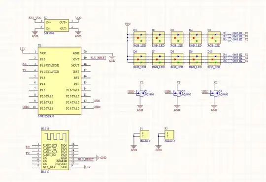
A diagram of how the RF device is connected to the barcode reading system.
