4

I've got a PIC18F with MSSP that I'm interfacing with a 24AA1025. I'm using MPLAB 8 and the functions from C18 to make my life easier. The only problem is that I've (supposedly) written a byte to the 24AA1025, but when I read it back, I get 0xFF instead of the byte I wrote.

Here's how I have the EEPROM wired up:

A0 - GND
A1 - GND
A2 - Vcc
Vss - GND
SDA - pulled up to +5 via 2.2k resistor, and connected to SDA on PIC
SCL - pulled up to +5 via 2.2k resistor, and connected to SCL on PIC
WP - Vss
Vcc - 5V

Here's my write function (now edited with working code):

bool I2CWriteByte( long address, unsigned char data)
{
    unsigned char ret;
    unsigned char control_byte;
    unsigned char high_address_byte;
    unsigned char low_address_byte;

    control_byte = (address >= 65536) ? 0b10101000 : 0b10100000;
    high_address_byte = (char)((address & 0x0000FF00) >> 8);
    low_address_byte = (char)(address & 0x000000FF);

    IdleI2C();

    // perform ack polling around control byte sending every time
    ret = SendControlByte( control_byte);
    if( ret == -1)
        return false;

    ret = WriteI2C( high_address_byte);
    if( ret == -1)
        return false;
    ret = WriteI2C( low_address_byte);
    if( ret == -1)
        return false;
    ret = WriteI2C( data);
    if( ret == -1)
        return false;

    StopI2C();
    return true;
}

Here's my read function (now edited with working code):

bool I2CReadByte( long address, unsigned char* data)
{
    unsigned char ret;
    // to do a read, first do part of a write but don't send the data byte, then send a new control byte with bit 0 set to 1 for read.
    // see 24AA1025 datasheet page 12
    unsigned char control_byte;
    unsigned char high_address_byte;
    unsigned char low_address_byte;

    control_byte = (address >= 65536) ? 0b10101000 : 0b10100000;
    high_address_byte = (char)((address & 0x0000FF00) >> 8);
    low_address_byte = (char)(address & 0x000000FF);

    IdleI2C();
    ret = SendControlByte( control_byte);
    if( ret == -1)
        return false;

    ret = WriteI2C( high_address_byte);
    if( ret == -1)
        return false;
    ret = WriteI2C( low_address_byte);
    if( ret == -1)
        return false;

    control_byte = (address >= 65536) ? 0b10101001 : 0b10100001;
    ret = SendControlByte( control_byte);
    if( ret == -1)
        return false;

    // now return value
    *data = ReadI2C();
    StopI2C();
    return true;
}

EDIT -- The all-important SendControlByte() function, which does the requisite ack polling:

bool SendControlByte( unsigned char control_byte)
{
    bool nack;
    bool ret;

    nack = true;

    while( nack) {
        StartI2C();
        ret = WriteI2C( control_byte);
        if( ret == -1)
            return false;
        if( SSPCON2bits.ACKSTAT == 0)
            nack = false;
    }
}

WriteI2C never returns an error, so I assume that it actually worked...

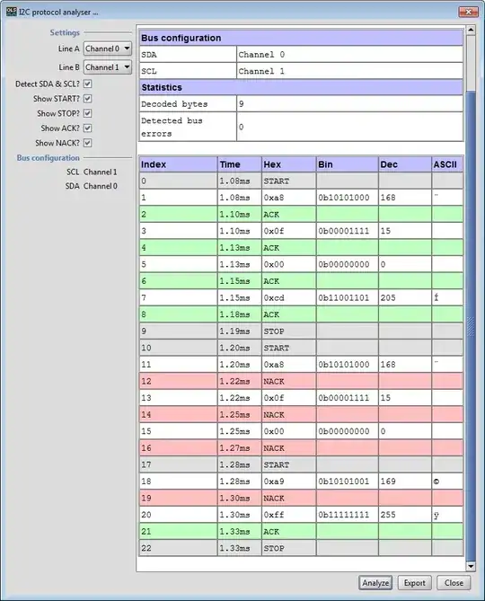
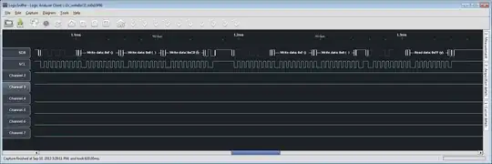
I used my logic sniffer's I2C protocol analysis tool, and it sure looks like all of the data is being sent/received properly:

enter image description here

Can anyone suggest something to do next for debugging? The control byte looks correct, as it is 0b1010 after START, followed by the block identifier, A0, A1, and R/!W. I have tested >64KB addresses and confirmed that B1 is set properly. My EEPROM has A0 and A1 grounded, so that looks correct as well. R/!W is low for writes and high just before the read. The only thing I haven't done yet is added a delay after the write, but I will give that a shot tomorrow.

EDIT -- The I2C analysis option does show what you guys have been saying:

enter image description here

Dave
  • 3,800
  • 24
  • 41
  • You certainly need a delay after the data write (try 10 ms to begin with, though I'd recommend using the acknowledge polling described when you're polishing it up later). Without it, the read is likely never performed, as the device won't respond to commands during a write cycle. My guess is that it returns 0xff because SDA remains high (since the device never pulls it low - it's busy!). – exscape Sep 11 '12 at 08:50
  • @Dave Hi dave you have done a commendable job with the thorough analysis tools that you have got.Can you tell what are the tools that you have used to debug I2c and capture the send signals and displayed as shown above. And i also would like to explain how the SendControlByte works,I know it is working with acknowledge polling but when i tried compiling with the code that you posted ..it did not worked well.I tried with c18. And what values have you given for true and false?.Thanks – Rookie91 Dec 06 '13 at 04:12
  • Hi @Rookie91, it's been a while, so let me try to remember. The software is from the Open Logic Sniffer project. A year ago I found it hard to get a build that worked, but the latest builds seem pretty good. Try this thread to get the download link: http://dangerousprototypes.com/forum/viewtopic.php?f=57&t=1198&sid=932583c3285d204d4b27ea4a63f3cab6. As far as true and false go, you can technically use anything you want, but 0 for false and 1 for true are typical. Or include and use its definition. – Dave Dec 11 '13 at 03:43

1 Answers1

4

My guess is that the problem indeed is that you need to delay after the write.

The device will be busy for roughly 3-5 milliseconds after a write, during which it will not respond to any commands. If you issue a read during this time period, the device will ignore it, and the SDA line will remain high - which would indeed lead to a result of all ones being read on the clock pulses.

First off, try adding a delay after the write, perhaps 10 milliseconds or so.
If that works, check the datasheet chapter on acknowledge polling, to improve the performance. In short, acknowledge polling means sending a write command over and over until the device acknowledges it, at which point you know that the write cycle is complete.

exscape
  • 1,172
  • 2
  • 12
  • 20
  • Actually one should wait for the EEPROM to acknowledge the write. The data sheets describes this (it's called *ACK polling*). That way you avoid a fixed delay and wait only as long as the write really takes (but OTOH it is a busy wait and needs the I2C bus). – hli Sep 11 '12 at 10:54
  • Agree. You should also check that the device acknowledges the read request before proceeding with the read of the data byte(s). – Adam Lawrence Sep 11 '12 at 10:57
  • Yes, it's clear from the logic analyzer trace that the chip isn't ACKing the command/address bytes for the read. This is exactly the sort of detail that the analyzer is supposed to help you find; be sure that you're making full use of it. Also, the I2C firmware routines (WriteI2C(), in particular) should have been detecting the lack of ACK and returning an error. Clearly, something is wrong there, too. – Dave Tweed Sep 11 '12 at 12:07
  • Thanks, guys, I will fix the code (and library files) now. – Dave Sep 11 '12 at 12:14
  • @hli I did mention that. – exscape Sep 11 '12 at 12:51
  • @exscape thanks again, while the delay was good to add to verify that the EEPROM code generally worked, ack polling was the key. I totally missed that detail when I was going over the datasheet... really sloppy on my part. – Dave Sep 11 '12 at 14:04
  • @exscape sorry, after all the talk about the delays I totally missed that :( I just parsed the text for 'ACK' and missed that... – hli Sep 11 '12 at 17:46