6

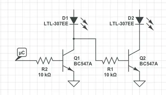
I want to control a 2 digit 7-segment LED with a MSP430 micro controller. The display has 8 input pins per digit (8th pin is the dot, which I do not need) and two ground pins (common cathode). The idea is to connect the first 7 pins from the µc to the 7 segments of both digits and then use another pin (the control pin) for selecting which digit to display. By switching fast between the two digits I would like to display a two digit number using 8 pins of the µc only.

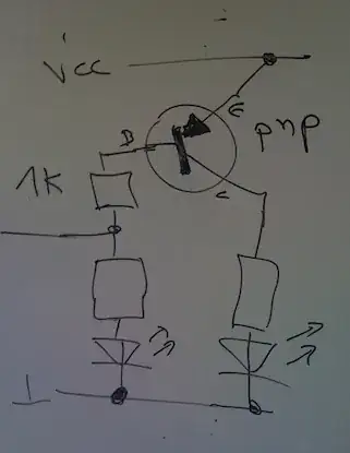
What I need is the following. We can abstract such that there are only two LEDs. If the control pin is LOW than LED1 is on and LED2 is off. If the control pin is HIGH then LED2 is on and LED1 is off. I know how to build this with a single PNP transistor (see picture below). However, this is not useful in the common cathode setting, since I want the switching gate "behind" the LEDs.

What I don't want to have

My question is, how to build such a circuit with one single transistor (and resistors of course). I think it has to be a NPN transistor.

This is my first EE question and I have little experience, so I hope I was able to make my question clear.

A.Schulz
  • 163
  • 5

2 Answers2

5

You are right about the NPN transistor, that is what you need in order to achieve that behaviour, however, since the µC would have to control the cathode of one of the displays, that would be a problem since most µC can only source / sink a few mA. Assuming each segment needs 10mA that would require the pin to sink 70 mA.

The most simple solution is to have two NPN transistors capable of sinking at least 100 mA (such as the common BC547).

Diagram bellow:

Diagram

Being D1 and D2 the 7 segment displays (please ignore the reference). The anodes on the LEDs will connect to the µC pins.

In this configuration only Q1 conducts when the µC outputs 1 and when it outputs 0 only the Q2 conducts.

Note
It might be necessary to add a high value pull-up resistor (for example 100 kΩ) to the base Q2.

Bruno Ferreira
  • 4,470
  • 2
  • 25
  • 36
  • Thanks a lot for your post! Based on your diagram I was able to build the circuit. However I had the problem, that there was still a small amount of current flowing through D1, when Q1 was closed. I was able to get rid of this effect, by adjusting the resistors R2= 1.8K R2=1K and using a small resistor (47Ohm) between the collector of Q2 and Vcc. As transistor I used the BC 546. – A.Schulz Sep 16 '12 at 08:41
4

The first answer is a reasonable starting idea. There are some things to keep in mind while implementing this.

Where the seven anodes of each LED module connect over to the MCU port pins it will be needed to insert series resistors in each line to limit the current to a safe value for the individual segments. The resistor value used would need to be:

Rseries = (VDD - VF (led) - VSAT (NPN)) / IF (led)

I would suggest a lower value resistor on the bases of the two NPN transistors. 2.2K would be more reasonable.

It will be necessary to put a resistor from the collector of the first NPN transistor up to the VDD supply so that when the first NPN transistor is OFF that there is sufficient BIAS to turn on the 2nd NPN transistor. I would use a 1K resistor for this. If this is not done then the 2nd transistor would be getting its BIAS through the supposedly off LEDs of the first display module. This can make some segments appear to be on when they shouldn't be.

Lastly the software that drives the LED display should make sure to drive all seven of the anode connections to the LEDs to a low level for a short time before the digit selector I/O to the NPN transistors is changed. Then after the digit selector is changed a short delay should exist before the segment pattern is then applied to the port pins for the now active display module. This will prevent ghosting of the segments from one display showing in the OFF positions on the other display when multiplexing at a high rate. The delays only need to be on the order of a third to half of a microsecond or so. Depending upon the frequency of the MCU being used this may be supplied by a few instruction cycles of the software being used to bit-bang the display logic.

Michael Karas
  • 56,889
  • 3
  • 70
  • 138
  • Your comment was very helpful. I had to modify the suggestion of the first answer, slightly. However it was different to what you were suggesting in the second to last paragraph. See my comment to the first answer. – A.Schulz Sep 16 '12 at 08:44