Looking at the schematics of the Pro Micro, the LED in PD5 (bottom-right) is connected to VCC instead of GND, same for PB0. Why? Shouldn't they connect to GND?

Looking at the schematics of the Pro Micro, the LED in PD5 (bottom-right) is connected to VCC instead of GND, same for PB0. Why? Shouldn't they connect to GND?
It works perfectly fine as is.
The output of a microcontoller can be set to high or low.
High is just connecting the output to Vcc through a transistor inside the processor.
Low is just connecting the output to ground through a transistor inside the processor.
All it changes is what value you have to write to the output pin.
If the LED is connected to ground, then you write a high to the output to make the LED light up.
If the LED is connected to Vcc, then you write a low to the output to make the LED light up.
No difference in function, you just have to use a different output value.
That said, some chips are better at sourcing current (better for output high) and some are better at sinking current (better for output low.)
If you need to get maximum brightness without damaging the chip and without using external transistors, then it matters which is which.
When in doubt, use an external transistor.
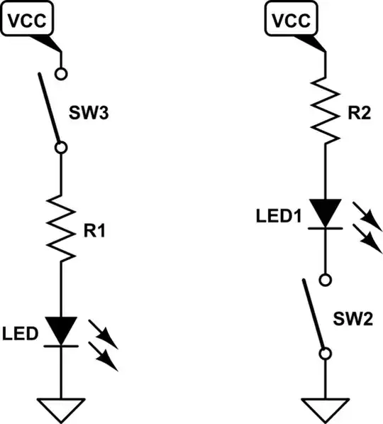
Instead of having the switch on the "high" (VCC) side, these LEDs have their switch on the GND side:
simulate this circuit – Schematic created using CircuitLab
The left circuit shows the more "traditional" solution where the LED is grounded.
In both cases the switch is a transistor inside the microcontroller.
In case of "high side switching" (left) a PMOS will do the work.
In case of "low side" switching (right), an NMOS will do the work.
The LED doesn't care what you do. The LED cannot tell the difference. If you apply enough voltage across it, it will light up.

Figure 1. LEDs can be connected to positive supply or to ground. Image source: 1 GPIO - multiple LEDs.
Note the direction of the arrow in the diode symbol. This is the required direction of current (from positive to negative).
With the circuit shown in Figure 1:
Your circuit is the same as Figure 1 but with R2 and L2 left out.
There is no real reason that those LEDs need to connect to GND. It is a design choice as to how to connect them. In the case shown the design choice may have been to be able to light the LEDs when a low logic level was commanded to the output pin. Another consideration may have been related to the default operational state of GPIO pins so as to manage power up and power down behavior.