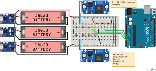
The batteries can NOT be connected in series when charging.
This will short out the battery. This is because the ground is not floating on USB hubs. Gnd will short out the lower V+ connected to it.
You would need 3 isolated USB wall chargers capable of 5W or 1A or more to charge in series.
You may add 2 LEDs with the anode (+) to 5V to indicate charging with the cathode (-) to 330 ~ 1K series R to CHRG low when active and STDBY low when done.
An actual current of 10mA is adequate which is V/R=I
The charge current depends on the onboard PROGramming resistor into a current amplifier. \$I_{BAT}=\dfrac{1V*1200}{R_{PROG}}\$ thus 1.2k = 1A
The battery chargers are linear regulators and only need 4.2V in but 5V is ok but gets warmer with 1000mA and may need heatsink from 3V discharged cell. (5-3)*1A=2W
If your USB Hub cannot drive 1000mA then it is slow to charge up.
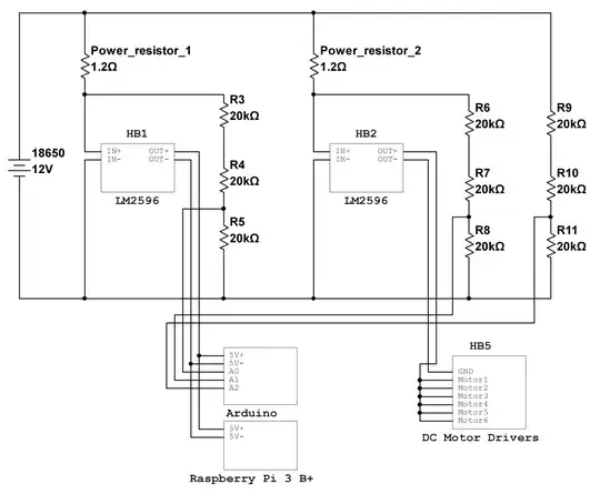
Your LM2596 will not generate split +/-5V supplies. Yes, it is true the intermodulation or having each Buck supply interference with simultaneous charge currents is not a good idea.
Although it is a good idea to decouple the motor power from logic Vdd and Vss but not with this PS design. Go to ti.com and register your email and choose a triple output design from their "Webbench" online in the browser with Java approval or Analog Devices.
Often a 3 secondary winding forward converter works best on a custom coil form. By tight mutual coupling of coils, the ratios of voltage are maintained while regulating off one for feedback. This is how PC PSU's generate all their voltages.

