25

I have seen people pulling up only the CS pin, so that when the microcontroller's pins are floating in the power-up, the microSD card is not corrupted.

Also, I have seen many people pulling up and down DI,DO and SCLK lines.

Some of the circuits that I've seen even connect pins 1 and 2 to Vdd/2 via a voltage divider that is formed between Vdd and Vss.

Which pins of the microSD card should be pulled up or high when interfacing a microcontroller with an embedded SPI interface and has the appropriate logic voltage levels?

microSD Card Pinout

abdullah kahraman
  • 5,930
  • 7
  • 59
  • 104

1 Answers1

21

The specification only makes mention of the 50K\$\Omega\$ pull-up internal to the card used for card detection. It talks about this in reference to the commands used to disable it. Search for "pull" to see all the mentions of it.

However, the SanDisk SD Card Product Manual is much more helpful. From Chapter 3:

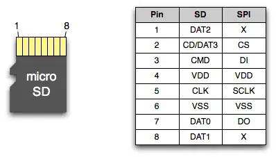
\$^2\$ The extended DAT lines (DAT1-DAT3) are input on power up. They start to operate as DAT lines after the SET_BUS_WIDTH command. It is the responsibility of the host designer to connect external pullup resistors to all data lines even if only DAT0 is to be used. Otherwise, non-expected high current consumption may occur due to the floating inputs of DAT1 & DAT2 (in case they are not used).

\$^3\$ After power up, this line is input with 50Kohm(+/-20Kohm) pull-up (can be used for card detection or SPI mode selection). The pull-up may be disconnected by the user, during regular data transfer, with SET_CLR_CARD_DETECT (ACMD42) command.

\$^4\$ The ‘RSV’ pins are floating inputs. It is the responsibility of the host designer to connect external pullup resistors to those lines. Otherwise non-expected high current consumption may occur due to the floating inputs.

So you need to add pull-ups to all unused pins to prevent high-current from occurring due to the inputs being floating.

For the SPI signals that you will be using, pull-ups are not required. However if your traces are long or running through a noisy section on your board, or if you are running a high clock rate, adding pull-up resistors will help to clean up your signals transitions.

embedded.kyle
  • 8,411
  • 2
  • 26
  • 44
  • 1
    Thanks for the answer. I am curious why a high current consumption will occur when an input pin is floating. – abdullah kahraman Sep 05 '12 at 16:41
  • 10
    It's because the signal may float into the metastable/transition region for CMOS circuits, where both PMOS and NMOS elements are turned on, and current flows continuously, wasting power and producing heat. During normal operation, signals should move through this region very quickly, so the wasted energy is low. See [this TI paper "Implications of Slow or Floating CMOS Inputs"](http://www.ti.com/lit/an/scba004c/scba004c.pdf) – Ben Voigt Sep 05 '12 at 17:54
  • @abdullahkahraman Ben nailed it. – embedded.kyle Sep 05 '12 at 20:22
  • Just curious, does pulling up or down matters? Can I pull down `DAT1` while pulling up `DAT2` or vice-verse? – abdullah kahraman Sep 08 '12 at 12:07
  • 2
    @abdullahkahraman Since SD Cards are CMOS, it shouldn't matter. With TTL you usually want to pull up to avoid wasting power. See [this forum post](http://forum.allaboutcircuits.com/showthread.php?p=16626#post16626) – embedded.kyle Sep 10 '12 at 12:30