7

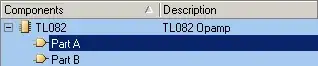
I'm learning custom library design in Altium Designer. I designed several libraries so far (BJTs, resistors, capacitors, etc), all worked without any problem. This time I tried to design an IC package (TL082 Opamp) which contains two distinct circuit elements in it.

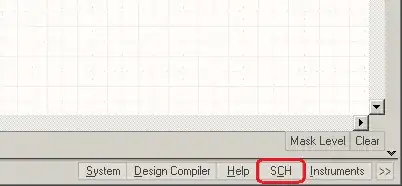
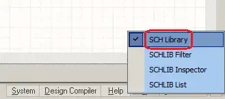
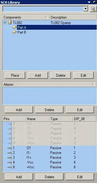
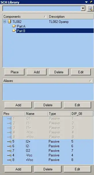
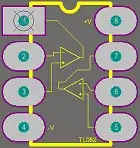
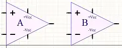
The PCB and schematic libraries look like:
PCB Library Schematic Library

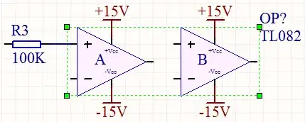
The problem is, when I try to use this library in circuit (schematics), the two Opamps behave like a solid one-piece object. I can't move each Opamp separately. Their relative position to each other doesn't change. When I drag one, the other one comes with it. I want to use one of the Opamps in a place far away from its brother, but they just don't want to leave each other.

Native libraries of Altium Designer don't do this behavior. For example, TL084 has four opamps in it, they all can be used independent from each other.
I don't want to use native TL082 library of Altium Designer in my circuit. My aim is learning to design libraries in Altium Designer.

The opamps look like this in the circuit:
Looks in circuit

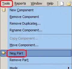
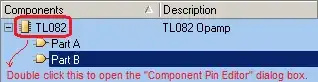
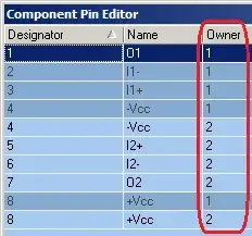
How do I separate these two Opamps from each other, so that I can use them independently in the schematic?

hkBattousai
  • 13,913
  • 31
  • 114
  • 190
  • 1
    Have a look at [this training video](http://videos.altium.com/trainingcenter/player.html?ep=1044) from Altium. It shows how to create a schematic symbol with multiple parts (an op-amp). You probably drew the two op-amps on the same sheet. – m.Alin Sep 05 '12 at 12:00
  • @m.Alin Thank you for your comment. That video explained everything. If you simply repost your comment as an answer, I will accept it. – hkBattousai Sep 05 '12 at 13:41
  • I'm glad it helped. You should accept your own answer. It explains pretty well the process. Mine would just be a link. I'm lazy like that :-) Altium has some great [training videos](http://www.altium.com/training/en/training-videos.cfm). And for more in-depth explanation, you can read the [training manuals](http://www.altium.com/training/en/manuals-and-downloads.cfm) – m.Alin Sep 05 '12 at 14:09

2 Answers2

10

1) Open the "SCH Library" panel:

enter image description here

2) Add a new part(s) to your libaray:

enter image description here

Now there are two different parts ("Part A" and "Part B") listed under your components name:

enter image description here

Each of them has a different design screen. Click on the one you want to design. Design the two parts separately.

3) Assign which pin belongs to which part:

enter image description here enter image description here

Notice that the pins 4 and 8 belong to both parts and always active. Pins 1, 2 and 3 are only active when Part A is selected. Pins 5, 6 and 7 are active only when Part B is selected. The pins of the non-selected part are always grayed out.

If the some of the pins do not match to their corresponding parts, alter the settings in the "Component Pin Editor" dialog box.

enter image description here

enter image description here

Change the pin order to state which pin belongs to which part.
1: Part A
2: Part B

That's all. Now we have two separate parts in one component library.

hkBattousai
  • 13,913
  • 31
  • 114
  • 190
2

I haven't used Altium Designer, but have worked with its predecessor PCAD. So this is how PCAD did it, Altium will probably use something similar.

You'll have to define a multi-part component, and create a symbol for each part. Those parts can be similar, like opamp A and B, or 4 NAND gates for instance, but may also have mixed types, like when you decide to create a separate part for the power connections.

In the connections table you link the symbol's pin designators to the physical part's pins, and also indicate which parts may be swapped.

stevenvh
  • 145,145
  • 21
  • 455
  • 667