I'm trying to understand this temperature sensor circuit I came across on a room Air-Conditioner controller (Want to build one myself).
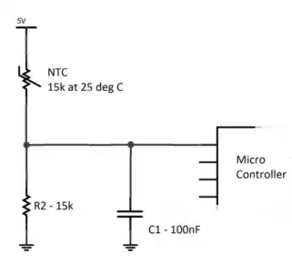
The sensor is an NTC type thermistor (15k at 25 deg C). What I collect is that the NTC along with R2 form a voltage divider, the output of which is fed into the ADC input of the microcontroller.
- What are C1 and C2 for? Do they form RC filters along with the thermistor? If that is the case, then the cut-off frequencies are 106.1Hz and 1.06Hz? These appear to be very low.
- What is R3 for? Is it limiting the current? If ADC input pins are high impedance, why limit the current?
- Do R3 and C3 form another RC filter? Then again the cutoff frequency is 3.386kHz. And there's nothing apparently operating at that frequency on the board. (The micro controller is connected to a 4Mhz external crystal and the board is powered by 230V/50Hz mains).
Thanks.