4

I would like to charge a capacitor bank with a 4.8 volt supply that I have. With the help received in response to this question, I now have a a useful current limiting circuit (shown below), that allows me to select a maximum current through a load. I have reimplemented the solution in CircuitLab . . .

enter image description here

The circuit is set to give a 480 mA max current. As the load resistance increases, the SER of the limiting circuit drops away. The following plot shows current through the load versus load resistance . . .

enter image description here

However, what happens if I want to charge a capacitor bank using this circuit. Where would I put it? Current needs to flow through R_sense to cause a voltage drop in order for the circuit to function. If I just add a capacitor after the sense resistor . . .

enter image description here

. . . and then measure the voltage across the capacitor, some crazy stuff happens . . .

enter image description here

What am I doing wrong ( -120V .. really )?

EDIT:

Following Oli's advice by adding a leakage resistor and paying attention to initial conditions . . .

enter image description here

.. I now get a logical looking output, although the voltage is not up to Vcc

enter image description here

If I place the capacitor where R_Load is,

enter image description here

Then the voltage of the cap jumps up to 4.8 volts immediately (which I'm guessing would draw a massive current, fry my supply, and negate the point of the current limiting circuit)

enter image description here

This looks pretty logical to me. If a cap is connected to an ideal voltage source, it will get an infinite current and be at 4.8 V instantaneously. What do I need to do in order to reproduce the effect shown in Oli's lowest plot?

learnvst
  • 1,213
  • 3
  • 21
  • 28
  • For the second simulation with the cap at the top, you need to set the cap voltage to 0V initially. I did this by setting the voltage at the MOSFET drain to 4.8V, the `.ic V(n001) 4.8` you can see next to the cap is the SPICE command to do this. This means both ends of the cap are at 4.8V hence there is no voltage across it. I'm not sure how you do this in Circuit Lab, if you can link to your circuit maybe I (or someone else more familiar with it) can help. – Oli Glaser Sep 05 '12 at 13:03
  • https://www.circuitlab.com/circuit/t974eh/opamp_cap_charge/ – learnvst Sep 05 '12 at 13:09
  • Okay, thanks. Unfortunately it seems there is no way to do this in CircuitLab yet. [They suggest](https://www.circuitlab.com/forums/modeling-and-simulation/topic/269p42w5/initial-condition-hint/) using a time controlled switch switching at T=0 as a workaround. CircuitLab is pretty, but it's not as sophisticated as SPICE - if you are planning on doing plenty of EE, then I'd advise getting to know SPICE (LTSpice is a great free version from LT, there are also other options like NI Multisim, TINA from TI, ngspice, etc) – Oli Glaser Sep 05 '12 at 13:27
  • Okay, I managed to use the switch to simulate the initial condition. Try this [edited version](https://www.circuitlab.com/circuit/7dga73/constant-current-cap-charge/) of your circuit. – Oli Glaser Sep 05 '12 at 13:39
  • Wow, thanks for the help Oli! So the current limiter in this case is controlling the discharge rate of the -ve plate. I eventually want to place a load across the cap that might spike huge current (hence the big cap). Would I be better modifying this circuit to us a Pch MOSFET and use high-side limiting? It is the supply that I want to protect, not the load. – learnvst Sep 05 '12 at 14:49
  • Yes, sort of - although the voltage at the bottom plate of the cap is falling (the plate itself doesn't "discharge") the cap is still charging at a constant current (the plates start at the same voltage, and end up ~4.8V apart - it doesn't care which plate changes relative to what, all that is needed is a difference between the two plates) If your load placed across the cap needs to be circuit ground referenced then a high side limit would be better, yes. If large current/voltage transients are possible then physically switching the cap over to the load might be a good idea (e.g. relay) – Oli Glaser Sep 05 '12 at 20:41
  • What would a relay do? Also, if i were to implement this circuit, would i need both plates of the cap connected to Vcc at switch on? – learnvst Sep 06 '12 at 09:56
  • The relay could be used to disconnect the cap from the charging circuit, and connect it to the load. This way if anything "nasty" happens during the discharge process then the charging circuit is isolated from it. You can use more than one relay, e.g. to switch capacitor out, then switch load in. This is just a thought, it may not be necessary depending on what exactly you are doing. Both plates of the cap do not need to be at Vcc (or ground if high side limiting) at switch on, this is just for the simulation. – Oli Glaser Sep 06 '12 at 12:08
  • I want to avoid relays and use the capacitor as a massive power store for a load that will require a little bit of power all of the time and the occasional brief busts of huge power. Ideally, the supply can just slowly top up any deficit in the storage between the load bursts. I want current limiting as I dont want the supply to see any load requiring more than ~480 mA. I thought that the main load would be connected across the capacitor. Once the cap is charged, it would just act as a power reservoir that kicks in once the current limiting circuit restricts flow form the source. – learnvst Sep 06 '12 at 13:59
  • Ah okay, if you need to supply current continuously as well as large pulses forget the relay then (I was thinking it was only for bursts of power, as in something like a welder) – Oli Glaser Sep 06 '12 at 14:39
  • Ok, cool. I still don't understand how the cap will not detonate my power supply at switch on. If both plates are at 0V (connected to ground because of the leakage), then the inrush will be crazy. . . . or do i put the power switch between R_sense and ground. Confused :s – learnvst Sep 06 '12 at 14:58
  • The inrush current can't ever be more than the limit set by the circuit (the MOSFET adjusts it's impedance to keep the current constant when limited). See the last graph in my answer - the current is flat at 480mA from the cap voltage starting at 0V and charging up to the supply voltage. This is what will happen at power on. – Oli Glaser Sep 06 '12 at 15:02
  • You see that R_load? That's a resistor, representing the load. Put the load there. – user253751 Aug 17 '20 at 11:45

3 Answers3

4

As Madmanguruman says, the capacitor is in the wrong place.

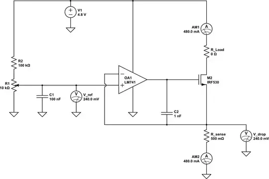
The opamp is trying to keep the voltages on it's inverting input the same as the non-inverting input, which is 240mV in your example above. To do this with just Rsense present, it must keep 480mA flowing through Rsense as you say.
Now, with the cap in series, it will actually work to charge the capacitor as you have it. However, the catch is that it will not be at a constant current, and the cap will only charge to 240mV, since this it what the opamp needs to keep the balance.
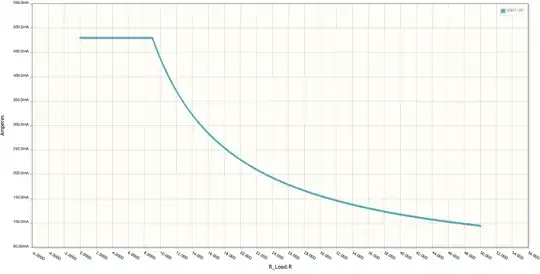
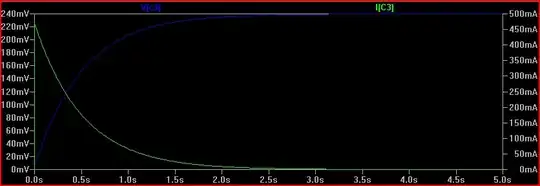
The cap does not pass DC, so the current is initially 480mA, and drops exponentially down to 0 as the voltage rises (and the voltage across the resistor drops)

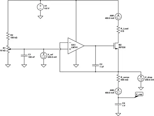
Another thing to understand here is that a simulation is only as real as you make it, and in some cases the ideal components cause problems. It's quite common for the simulator not to converge or produce odd results if there is no DC path available. Also with a transient simulation, you sometimes need initial conditions set to observe a process.
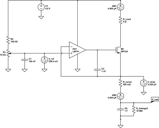
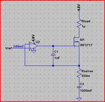
For example, if I simulate the above circuit in LTSpice with an ideal 1F capacitor, the simulation does not converge (never finishes) If I add a high value of parallel resistance (10MΩ, this is actually very conservative for such a large value, probably be much lower) to provide a DC path, and (very roughly) simulate real world imperfect capacitor leakage, the simulation works:

Cap Charge not constant

Simulation:

Cap Charge Simulation

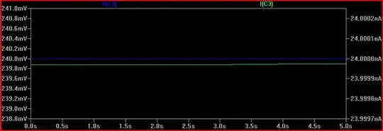
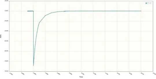
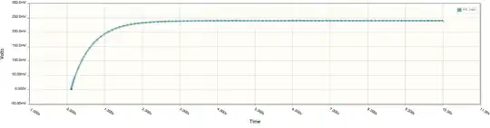
The 240mV is produced by the 24nA across the 10MΩ resistance (24e-9 * 10e6 = 0.24V) However, the cap starts the simulation at 240mV. Is this what will happen in real life? It's unlikely, so we need to simulate things as it will be when power is switched on, or at least with the cap starting with 0V across it. The reason this happens (in SPICE at least) is because there is an initial DC operating point simulation done before the transient simulation starts.

If we do the same simulation with an initial condition specified, we can see the "interesting" bit that happens prior to reaching a steady state:

Cap Charge with initial condition

So remember to be aware of the difference between ideal and real world components. If simulation results appear strange, then try adding some ESR/ESL (equivalent series resistance/inductance) and parallel resistances to simulations that correspond with the components you intend to use (datasheet will give values usually)
Also be aware of tolerances, for which monte carlo simulation is very useful.

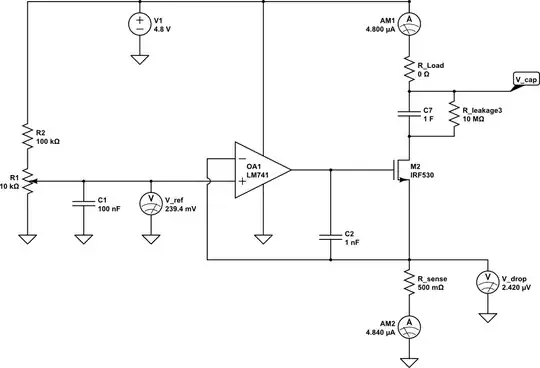
Finally, here is the circuit with the cap placed in the right place, (although you may want high side current limiting in your final circuit):

Constant Current Cap Charge

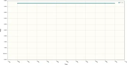
Simulation of current through cap and voltage across it, notice the constant 480mA up until the cap is fully charged to 4.8V (initial condition used again to see the cap charging):

Constant Current Cap Charge Simulation

One last thing, make sure you do not use the LM741 in your final circuit, it's completely obsolete. Choose a decent general purpose rail to rail input/output opamp (rail to rail means it can swing all the way to each rail at the output and handle voltages up to each rail at the input, many opamps, including the 741, cannot do this - another departure from the convenient world of ideal components)

Oli Glaser
  • 54,990
  • 3
  • 76
  • 147
  • Many thanks for another outstanding answer. However, I cannot reproduce your final figure. See edits for details. – learnvst Sep 05 '12 at 12:55
2

Current needs to flow through R_sense to cause a voltage drop in order for the circuit to function.

EDIT: After looking a second time at your circuit, I realized that there are some limitations.

The absolute maximum voltage that you'll be able to charge the capacitor to is \$V_{out(OA1)} - V_{th(M2)} \$ which isn't going to be terribly useful.

\$ V_{out(OA1)}\$ is going to be less than the 4.8V supply, since a 741 op-amp isn't rail-to-rail output. Let's assume it can output 4.8V for now. The worst-case gate-to-source threshold \$V_{th}\$ for an IRF530 is 4V. This leaves only 800mV of capacitor voltage before the MOSFET will pinch itself off (there won't be enough gate-to-source voltage to keep it turned on).

As you can see, you're able to limit the capacitor current, but the voltage will be very low due to the circuit configuration you have.

The -120V is obviously a simulation 'oops'. The capacitor should start out like a short and ramp up to its final value smoothly.

Adam Lawrence
  • 32,921
  • 3
  • 58
  • 110
2

I have looked at the same question: How to charge a supercapacitor quickly to 5V? The main problem is that the throttling component - be it a resistor, MOSFET, linear regulator - would most likely dissipate a significant amount of heat. If it's an IC that limits the current, then that component might fail, or shut down temporarily (thermal protection), and take longer than expected to charge the supercapacitor.

However, there are some solutions that generate very little heat, or that can handle the heat robustly:

Solution 1: Throttle the current with a switch-mode circuit and an inductor (very little heat will be generated). But the control circuitry is not trivial.

Solution 2: Use a special linear charging IC designed for the job. I concluded the LTC4425 is good for the job, since it has a mode where it will charge as fast as possible while maintaining its temperature within the acceptable limit. In the spec sheet, the thermal dissipation limit was around 2 Watts or so. That only applies if the thermal pad is soldered down, however.

The 2W thermal dissipation limit means, when the supercapacitor is empty, the LTC4425 will charge with initially 372mA (since 5V * 0.372A is roughly 2W), and then increase the current from there on. As the supercapacitor voltage increases, the heat loss in the LTC4425 decreases, and it can charge faster - up to the 3 Amps when the supercapacitor is already at 4V and above.

So this inspired the best solution, in my opinion:

Solution 3: Combine the LTC4425 with a power resistor in parallel. This way, the power resistor will handle most of the initial charging current and heat, while the LTC4425 will complete the supercapacitor charging much faster than the resistor would by itself.

Here's a calculation I made: If I can draw up to 2 Amps from a 5V source, I would set the LTC4425 current max limit to 1.7A, and connect it in parallel with a 3 Ohm resistor. In combination, the charging current is relatively flat near 2 Amps until the supercapacitor is charged. That's as fast as the power source allows, without any part overheating.

enter image description here

Sebastian
  • 21
  • 1