0

Got few questions about the input/output pins of a crystal circuit. enter image description here
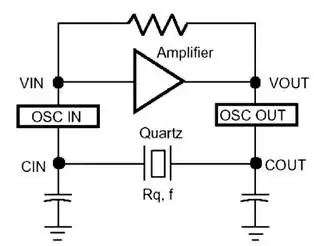
As shown above, it's a common clock circuits. My question is: 1. If we want to measure the waveform of the clock, which pin should we probe and why? 2. In the internal circuits inside the IC, which signal (IN or OUT) is used for the clock source of the internal circuits and why?

Thanks!

Nobody
  • 591
  • 1
  • 9
  • 20
  • If possible, configure one of the I/O pins to output the internal core ALU clock. Many support this feature. A scope probe can load down the oscillator and pull the frequency. That depends on the oscillator, though. Some are designed for low power and run "light" and would be affected strongly by a probe. Many are designed to run overly-hot (because they expect "idiots" to use them and don't want after-sale calls about problems) so their class-A inverter has plenty of drive and can handle the extra load. So it depends. – jonk Sep 01 '18 at 14:27

1 Answers1

1

You should measure the waveform from the OSC_OUT pin as that point is driven by the amplifier. Then adding some extra loading on that pin (the loading of the probe you will use to measure the voltage) is not an issue.

If you measure at OSC_IN you could be unlucky and disturb the circuit so much that it stops oscillating !

The internal circuit should and will do the same as you should so use OSC_OUT. That pin will not be used directly though there will always be additional buffer circuits present to feed the signal to all other circuits.

Bimpelrekkie
  • 80,139
  • 2
  • 93
  • 183