2

In my textbook, there are two interrelated equations.

 1. wb = wt / (1 + R2/R1)
 2. wb = wt / Ao

where

 wb = break/cutoff frequency
 wt = unity gain frequency
 Ao = DC gain
 R1/R2 = standard resistors

These equations were derived from a simple and standard closed-loop inverting amplifier.
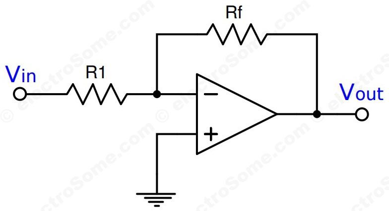
enter image description here From: https://electrosome.com/wp-content/uploads/2016/11/Inverting-Amplifier-using-Opamp-Circuit-Diagram.jpg

 G = - R2/R1

I understand the derivations of these equations separately, however cannot define the semblance between them.

For voltage gain G, isn't Ao = G? And from that, the +1 becomes an issue. I hypothesize that there is an assumption involving a << or >> I am overlooking.

Update: Upon further research, I have come across "feedback factor", often denoted by β. My logic follows for the non-inverting configuration given:

 Ao = G = 1 + R2/R1

However, the fact remains that I am unsure as to accounting for the +1 for the inverting configuration.

JRE
  • 67,678
  • 8
  • 104
  • 179
ennell
  • 21
  • 4

1 Answers1

1

For voltage gain G, isn't Ao = G?

There are two gains: The open loop gain and the closed loop gain.

\$A_0\$ is the open loop gain a low frequencies (before the cutoff frequency) What you have called G is the closed loop gain, which is the -R2/R1 for the inverting configuration you have.

With that, the open loop gain of the opamp over frequency could be modeled as:

$$ A_{ol}=\dfrac{A_0}{\frac{s}{\omega _b}+1}$$

Once you pass the cutoff frequency, the gain decays at a rate of 20dB/dec.

In reality, the closed loop gain is also frequency dependent (it has a bandwidth). If you start from the definition of the output voltage for an opamp: Vo=Aol(V+ - V-) you arrive at:

$$G=\dfrac{-R_2/R_1}{\frac{s}{\omega _A}+1} $$

Where \$\omega_A=\frac{\omega _t}{1+R_2/R_1} \$.

Hope this helps.

Add:

As per your new question in the comments—I think you are confusing 2 things. First, I don't know the naming convention your book uses, but when you say:

  1. wb = wt / (1 + R2/R1)
  2. wb = wt / Ao

There is something wrong about this. I mean, one is the cutoff frequency for the closed loop gain (1) and the other (2) is the cutoff frequency for the open loop one. Yet, they're both named the same in your text.

For the inverting amp, the closed loop gain is already given:

$$G=\dfrac{-R_2/R_1}{\frac{s}{\omega _A}+1}$$

For the noninverting one:

$$G=\dfrac{1+R_2/R_1}{\frac{s}{\omega _A}+1} $$

And the cutoff frequency, \$\omega_A\$, is the same for both (which is your first definition of \$\omega _b\$). \$A_o\$ is indeed the open loop gain at low frequencies.

Big6
  • 5,534
  • 1
  • 18
  • 23
  • Yes, this makes sense. However Ao represents DC closed-loop gain, not open-loop gain. And at DC, gain = -R2/R1. And the derivation you performed is how I receive my first equation. My issue is drawing the connection between that and my second equation (relating Ao to 1 + R2/R1). – ennell Aug 30 '18 at 03:54
  • Tom Ato, evaluating the given formulas it is evident that Ao is, of course, the open-loop gain at very low frequencies (including DC). – LvW Aug 30 '18 at 08:27
  • @TomAto Hope the edit will help. – Big6 Aug 30 '18 at 15:39
  • Here are the derivations if they help. Again, identical notation is used. (1) https://ibb.co/cZFWf9 (2) https://ibb.co/dWypYU – ennell Aug 30 '18 at 18:51
  • In the first link, the closed-loop gain cutoff frequency (1) derivation uses the open-loop gain cutoff frequency equation (2). Those frequencies are not the same? – ennell Aug 30 '18 at 19:09
  • @TomAto The first image is the closed loop gain and the second one is the open loop one. Those frequencies are not the same (look at the denominator of the 's' term, that's the cutoff freq.). Those are different – Big6 Aug 30 '18 at 19:44