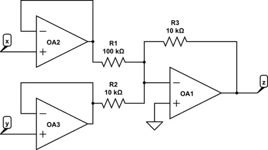
I'm trying to implement the following schematic of a simple analog computer

The inputs are x and y, according to the text where I found this diagram the circles represent voltage dividers or potentiometers.
There are some things I dont get, for instance the divider in the feedback loop is \$ \frac{1}{k}\$ and it also states that k is between 0 and 1, so that means that \$ \frac{1}{k}>1\$, that implies that the divider should actually be an amplifier instead?
This is how I implemented it:
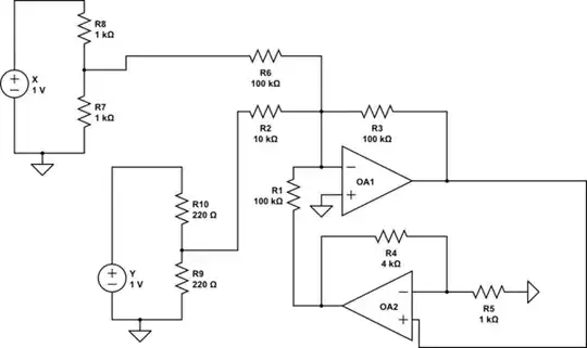
simulate this circuit – Schematic created using CircuitLab
With the resistor values I selected for the circuit, a=b=0.5, and \$\frac{1}{k}=5\$, which means that the final equation is supposed to be \$-0.2(0.5x+5y) \$. However, if one analyzes the circuit using superposition, we have:
$$v_o=-(ax+10by+\frac{1}{k}v_o)$$
or
$$v_o=\frac{-k(ax+10by)}{k+1}$$
What am I doing wrong? how is the circuit supposed to be to in order to get the correct output \$v_o=-k(ax+10by)\$?