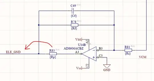
I'm working on the bias driver of an EEG system to remove the common mode signals from the channels. The output stage consists in a active inverting low-pass filter (I used an AD8606). Due to international medical standards it's mandatory apply a protection resistor to limit the current flowing through the body in case of fault. Depending of specific system and its stability requirements, this resistor can be placed inside or outside the feedback of the active filter (or also split).
In my case the system can work without stability problem either with the resistor inside and outside. But I have a strange behavior. If I keep the resistor inside the feedback most of the common signals disappear except for the 50Hz component, also improving the filter gain.
The first image shows the power spectrum of channels with a filter's gain equal to 1, with all the common signal present:
In the next image the effect of filter with a gain of 10 but the 50Hz component again present
But if I move the resistor on the outside (the red arrow in the schematic above describe the change) the 50Hz component disappear.
I know that maybe the context is too specific, but I'm wondering what are the consequences of putting the resistance inside the filter' feedback on its behavior? I know that there are no difference except for change the output impedance of filter.
Any suggestion on what's happening?
EDIT
Just to be clear, in the following figure you can see the model of the system applied on the user. All the parallel RC couples represent the skin/electrode interface and the circuitry on the left of the BODY block is the model of the EM interference which is the source of common signals.


