8

I'm completely new to the world of PIC Microcontrollers and electrical engineering so please go easy :)

Anyway, I managed to program my PIC 16f627 to turn on three LEDs when push button (trigger button) is pressed and start a shut down sequence (basically each LED toggles off one after another with a 5 second delay in between) when another pushbutton is pressed (reset button). I've been testing this on a Velleman's K8048 PIC Programmer/ Experimentation board. PINs RA0 and RA2 are the inputs for the trigger and reset pushbuttons respectively while pins RB0, RB1, and RB2 are the output pins for the LEDs.

Working with the experimentation board is great but I want to move this to an actual circuit. The problem is I have no idea where to start. I've bought 3 LEDs (3.3 Volts each), some pushbuttons, and wire and I've constructed the following circuit:

Circuit

(sorry for the horrendous schematic)

In the circuit I constructed, I first tested to see if the LEDs would work with 3 1.5 Volt AA batteries and they worked fine so I figured resisters wouldn't be necessary.

This does not work, however, and I'm totally lost. For reference, here is my code for the PIC. Its written in C using MikroC. It works on the experimentation board so I don't think its a problem

void main() {
    TRISB.RB0 = 0;
    TRISB.RB1 = 0;
    TRISB.RB2 = 0;
    PORTB.RB0 = 0;
    PORTB.RB1 = 0;
    PORTB.RB2 = 0;
    CMCON = 0x07;
    TRISA = 255;

    for(;;){
            if(PORTA.RA0 == 1 && PORTB.RB0 == 1 && PORTB.RB1 == 1 && PORTB.RB2 == 1){
                         delay_ms(5000);
                         PORTB.RB0 = 0;
                         delay_ms(5000);
                         PORTB.RB1 = 0;
                         delay_ms(5000);
                         PORTB.RB2 = 0;
            }
            if(PORTA.RA2 == 1){
                         PORTB.RB0 = 1;
                         PORTB.RB1 = 1;
                         PORTB.RB2 = 1;
            }
    }
}

Any help would be greatly appreciated. Thanks!
Oli Glaser
  • 54,990
  • 3
  • 76
  • 147
Shahmeer Navid
  • 189
  • 1
  • 2
  • 3
    Please please please use [Fritzing](http://fritzing.org/). It's free, does 90% of the work for you, and helps your schematic diagrams easier to read.. – Ignacio Vazquez-Abrams Aug 30 '12 at 05:18
  • 1
    Please read http://electronics.stackexchange.com/a/28255/4512. – Olin Lathrop Aug 30 '12 at 12:06
  • 7
    I think having an account for 10 days and this being Shahmeer's first question is an excuse for "dumping crap like this on us". Certainly Ignacio's approach of asking nicely is more likely to get a positive response than berating the new guy...unless your goal is to prevent new people from sticking around. – ajs410 Aug 30 '12 at 16:16
  • 5
    @ajs410 - we all know this is Olin's pet peeve, and while I don't always agree with his wording I agree with his principle. The fact that OP apologizes for the horrendous (his own words) "schematic" means that he knows well that it's not OK. Then why does he still post this thing? For me it doesn't have to be EDA-created, I think I'd rather see a pad-and-pencil drawing. – stevenvh Aug 31 '12 at 00:11
  • 2
    He's new, like a lot of other new members here (myself included). Give him a break. Shahmeer, give Fritzing a try. It's nice and easy to use, and will help you better explain your question. On another note, I strongly oppose Ignacio's choice of words. – capcom Aug 31 '12 at 02:59

5 Answers5

11
  1. Firstly, you always need series resistors with the LEDs when driven from a voltage source (e.g. battery, DC supply, etc)
    This is because LEDs have a non-linear I-V curve, which looks like a high impedance up to the threshold voltage of the LED then rises very sharply, so it means with a very slight change of voltage the current changes a lot, making it almost impossible to set the current to a stable value in this manner.
    By using the correct value series resistors, you ensure the current cannot rise enough to damage the LED.
    To calculate the resistor value you need to know the LED forward voltage (Vf) then subtract Vf from supply voltage and divide by desired current, e.g for a 5V supply, a 2V Vf and 15mA:

    (5V - 2V) / 0.020A = 200Ω (The standard value of 220Ω will do - if you don't have this then aim for anything between 150Ω and 600Ω for a 20mA to 5mA range)
    This is assuming a typical 5mm or 3mm LED of 20mA max operating current.

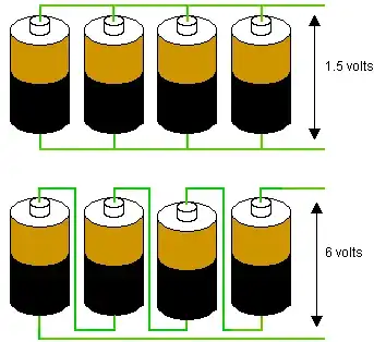
  2. Although it says "3 x 1.5V Battery in Series" in your schematic, the batteries look like they may be actually connected in parallel. T confirm, the batteries need to be connected end to end like the bottom diagram in this image:

    Parallel and Series connections

  3. You need decoupling capacitors present between the microcontroller Vdd and ground. I won't go into detail (search on here, there are many good answers on this subject) but they are basically to provide the microcontroller with a low impedance local energy reserve for high frequency current demand, which the power supply cannot respond to quickly enough.
    Ideally you should place one (100nF or 1uF ceramic is pretty standard) across the power and ground pins, as near to the pins as possible.

  4. Make sure you are using the internal oscillator if you have no crystal present. Your code does not show the config bit settings, if you have left them out you need to add them to ensure the microcontroller is setup correctly. The CCS manual should tell you how to do this. Also in the config bits, make sure the Watchdog Timer is set to off, otherwise your micro will continually reset (unless you call the WDT clear command regularly)

  5. Make sure that you have the LEDs the right way round.

  6. Make sure you have the MCLR pin tied high, otherwise your PIC will be held in reset (unless you turn MCLR off in the config bits) This is usually done with a resistor to Vdd, value around 10kΩ. The datasheet will have an example of this in the reset section. (thanks to ajs410 for mentioning this)

Oli Glaser
  • 54,990
  • 3
  • 76
  • 147
  • Thanks alot for the comments, they were really helpful. All those aside however, should I have connected the PIC in any other way or are the additions you've listed all I need? – Shahmeer Navid Aug 30 '12 at 05:28
  • 2
    One other thing is that you probably need pulldown resistors on your button pins, to make sure the pin is at logic low when the button is not pushed (unless you have internal pulldowns on, but I think that PIC will only have pullups available) It's hard to be sure of things with the schematic like it is (e.g. non standard symbols, no pin numbers/names, etc) I would get hold of some PCB/schematic capture software (e.g. Eagle[popular/free for non commercial], Kicad[popular/free], Diptrace[cheap], Altium[££££'s], etc) and use that in future. – Oli Glaser Aug 30 '12 at 06:01
  • 1
    6. Don't forget a pull-up resistor on the MCLR pin. Or set the configuration bit that uses the internal pull-up, if available. – ajs410 Aug 30 '12 at 16:13
2

Button function is simple. When we push a button, two contacts are joined together and connection is made. Still, it isn't all that simple. The problem lies in the nature of voltage as an electrical dimension, and in the imperfection of mechanical contacts. That is to say, before contact is made or cut off, there is a short time period when vibration (oscillation) can occur as a result of unevenness of mechanical contacts, or as a result of the different speed in pushing a button (this depends on person who pushes the button). The term given to this phenomena is called SWITCH (CONTACT) DEBOUNCE. If this is overlooked when program is written, an error can occur, or the program can produce more than one output pulse for a single button push. In order to avoid this, we can introduce a small delay when we detect the closing of a contact. This will ensure that the push of a button is interpreted as a single pulse. The debounce delay is produced in software and the length of the delay depends on the button, and the purpose of the button. The problem can be partially solved by adding a capacitor across the button, but a well-designed program is a much-better answer. The program can be adjusted until false detection is completely eliminated. Image below shows what actually happens when button is pushed.

Read more: http://romux.com/tutorials/pic-tutorial/push-buttons#ixzz43cAbVcWR

john
  • 21
  • 1
2

I highly recommend the O'Reilly series book "Designing Embedded Systems" by John Catsoulis for someone in your position. There's an "Electronics 101" Chapter that will bring you up to functional speed pretty quickly, and other on practical construction.

Scott Seidman
  • 29,274
  • 4
  • 44
  • 109
2
  1. Do not exceed 5V, your PIC could get burned above 5V voltage level. You can use 9V batteries or AC/DC adaptor with a linear voltage regulator like LM7805 to produce 5V for your circuit. How to wire:

    http://stuff.nekhbet.ro/2006/06/18/how-to-build-a-5v-regulator-using-78l05-7805.html

  2. Like most of said: Don't forget to supply MCLR pin with a serial resistor. You can use pull-up configuration to reset your PIC. Here's the link for the schema: http://www.mcuexamples.com/push-buttons-and-switch-debouncing-with-PIC.php

  3. Always use a serial resistor before a led. It'll save the led from getting burned and decrease the power consumption. For 3.3V leds 220 or 330 ohms would be fine.

Hammers
  • 69
  • 8
1

In addition to what the others have written: don't assign to individual PIC output pins, like for instance "PORTB.RB0 = 1;". Instead, make the bit change in a byte sized variable, and then write that variable to the port.

You can either

  • take my word for it,
  • read up on the "read-modify-write" issue, or
  • suffer the consequences
Wouter van Ooijen
  • 48,407
  • 1
  • 63
  • 136