-2

I have an old Yamaha SPX90 digital effects processor that the smps has packed it in. I have been trying seemingly to no avail to revive that smps. I have one more attempt at it after rebuilding the transformer 5 times. If that fails then I have no other option than to build a linear supply for it that will live in a giant box outside the unit. I'm finished wasting time trying to fix the smps which is noisy and should not have been used in an audio device in the 1st place. Don't care about weight, expense or size ... linear for audio at all costs. Why do you think that pro audio amps don't use cheap power supplies ? and they weigh a ton ... I just fixed a Peavey Cs-1200 and it was a pig. But it works like a charm now which makes me look like gold as a soundman. We use that amp for sidewash monitor and it makes a huge diff for the stage sound. Washing the stage with the front show with all the effects.

Here is the schematic that I have proposed and I am not really an engineer but have done some in the past. I am pretty experienced at troubleshooting just about anything even without a schematic ... I use the force. I'm a fly by the seat of your pants, Luke Skywalker troubleshooter when schematics are missing and a master when I have a plan.

I need an +/-18 volt supply as well as a +5v supply. The +/-18 feeds another set of regs (+/-15v) that in my mind is just stupid. Regulated then regulated again. And then the stupid engineers didn't regulate the 5v supply on the smps 5v rail. How nice of them to rely on an unpredictable smps 5v supply. As a side note the smps says it's regulated but I'd trust an LM78xx any day over an smps regulated supply.

Well here's my schematic for a linear with a few options for the 5v rail. Not sure which way to go with it at this point. Any pointers would be appreciated. This should be an easy one for all the experts out there. I am pretty sure I can do this on my own, only question is about how get the 3rd supply rail for 5v from a single transformer or two transformers ? ... and what VA rating for the tranny(s). The unit says is uses 20 watts so I'm thinking 25 to 30 VA for a safety margin ? Hard to say which supply uses more power but I'd hazard a guess and say the op amp +/-15 uses more power than the 5v digital supply. The +/-18 feeds two regs +/-15 for the op amps for the audio ... the 5v rail for all the digital stuff and there's quite a bit of that but the whole unit uses 20 watts so ...

enter image description here

And here's the whole digital/audio section ... enter image description here
enter image description here

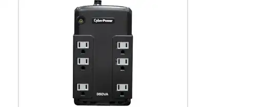
The +/- 18v supply feeds two more regs on the main brd. JRC 7815A and 7915. They don't have heatsinks but are well heat dissipated being mounted on a large ground plane. The 5v supply is unregulated after the initial output from the smps.
  • Welcome to SE.EE. Important missing info: current draw, or power consumption of the effects processor. – awjlogan Aug 15 '18 at 11:49
  • Thanks for edit. Next missing info: power consumption of the +/- 18V and +5V (if possible). Your main concern is going to be heat dissipation. As a guess without detailed info, I would go with linear for the +/- 18V (probably for the analog circuits) with a simple switching regulator after the smoothed rectified line for the +5V line (digital). – awjlogan Aug 15 '18 at 11:56
  • 3
    1) This question is a result of [this question](https://electronics.stackexchange.com/questions/390520/smps-transformer-issues/390532#390532). 2) The engineers are NOT stupid. As I said at the other question, the 5V of the SMPS has feedback, the +/- 18V follows. The 5V doens't have to be 'audio proof', _and_ has feedback, but the +/-18V feeds the opamps, so it has to be more stable. Probably after the 18V SMPS, there is a 7815/7915 **linear** regulator or so, to make the symmetrical voltage more smooth and 'audio proof'. Be careful to call someone stupid if you don't know how something works! – MartinF Aug 15 '18 at 12:46
  • Very difficult to say which rail uses more power ... I'm gonna guess the op amps and audio stuff on the +/-18v rail is high and the 5v digital is low. It really doeasn't matter as long as the overall power is met on either rail ... make them both able to supply way more than is needed within reason. – Kevin Smith Aug 15 '18 at 12:56
  • 1
    As I told you before: Post the schematic of the original SMPS, and ask if people can somehow figure out how much current it was able to deliver originally. If the two TO220's on the left of the PCB are 7815 and 7915, you know that you only need 1A max. for the +/- 15V, as that's what the 78xx can deliver max. You can then even rely on those regulators on the PCB, and provide a semi-regulated, high-ripple +/-18V to the PCB. Than you only need to worry about the 5V. You could use something like a LM2596-5.0 for that. – MartinF Aug 15 '18 at 12:58
  • 2
    @KevinSmith you have some fundamental misunderstandings here. Almost certainly the digital draws more power - a set of opamps is not going to draw much. And it does matter: a 20W supply is a very, very different beast to a 1W supply. Follow MartinF's suggestion above, and we can move forward. – awjlogan Aug 15 '18 at 12:59
  • Martin, wasn't calling YOU stupid ... there are engineers that are not worth there spit and I have worked with many of them. I rebuilt a test rig built by an engineer that had no idea about digital electronics and made his test rig run far more efficiently after I got hold of it. Some guys don't get it and I have had to rework there mistakes on many occasions. I may not know enough about analog but I know my digital and how mistakes can be made. I took your advice as gospel, have not questioned it so far ... I built the transformer as per YOUR instructs ... I have not powered it up just yet. – Kevin Smith Aug 15 '18 at 13:06
  • What are you guys listening ??? The whole rig draws 20 watts. what are you talking about Martin with 7818 and 19's ... I was talking to you about the original smps and nothing more. I used ALL your suggestions to rewind that transformer. Don't kno if it wrked yet cuz haven't powerd up yet. If it FAILS, I have to build a linear to replace the crappy smps. Nearly every owner of a piece of sound equipment curses smps units. They are cheap junk ! – Kevin Smith Aug 15 '18 at 13:15
  • I posted a very simple linear PS schematic and asked only about power issues for the OVERALL power. AT 20 WATTS for the whole unit how much VA units would I need for both rails ? If awjlogan says the digi will use more power then say by what percentage approx. This is a simple audio device not a NASA rocket. – Kevin Smith Aug 15 '18 at 13:20
  • 3
    @KevinSmith Martin/me are not having a go, but want to provide a good solution. If those two components in your picture are 78/9xx regulators without heatsinks (looks like it, can you take a closer picture?), that would suggest that *at maximum* the analog supply is <1W, so you need ~20W on your 5V rail. That would be a very hot and hard to engineer linear supply, so you want SMPS there. – awjlogan Aug 15 '18 at 13:23
  • So Martin, after following all your instructs the unit does not power up. So I have no other option other than to build a linear supply for he unit. All components have been checked and recheck in and out of circuit. I somehow knew trying to revive this smps was a huge waste of time. Definitely going to build a linear for it. So all I need to know is how to take my initial linear schematic and integrate the 5v supply and figure out what type of transformer I need for the 3 supplies and what VA rating. – Kevin Smith Aug 15 '18 at 13:37
  • 3
    @KevinSmith: I know you weren't calling _me_ stupid, so I took no offence from that. But I don't like that you call _other_ engineers stupid, when you might not have understood what they were doing. I've seen before that an SMPS feeds a linear regulator when there's sensitive audio circuits involved. It makes perfect sense to me, so why do you call them stupid? Now, having said that; I might be misunderstanding your posts, but in general they make me feel disrespected. E.g. you said: "What are you guys listening ???" That crosses my boundaries, so I'm sorry, but I'm out. Have a good day. – MartinF Aug 15 '18 at 13:39
  • You obviously misunderstood me ... you were talking about 7818's an 7819's when our last conversation was about an smps power issue. You asked me to post a new question about a linear power so I did and you said I was talking non-sense. Well did I do up the linear schematic ? I did and I think I did a pretty good job considering I don't have an engineering degree. I did exactly as you said. Now you dis me cuz I just happened to work wih some engineers who didn't know there stuff and I don'y just take every word as gospel from them. Believe it or not they do make mistakes. But ya finished. – Kevin Smith Aug 15 '18 at 13:49
  • I'll get this thing working without any help from this group ... my strength is persistence and patience. – Kevin Smith Aug 15 '18 at 13:58
  • Possible duplicate of [SMPS transformer issues](https://electronics.stackexchange.com/questions/390520/smps-transformer-issues) – winny Aug 15 '18 at 14:32
  • @winny Not a duplicate - follow up question, ranty but there is an interesting problem in it at least :) – awjlogan Aug 15 '18 at 14:37
  • 1
    @awjlogan Too similar and should have included a link to the original question for my taste. – winny Aug 15 '18 at 14:50
  • The original question was about how to repair the old SMPS for the unit. MartinF was the only one to chime in on the topic. Since I was unable to revive the old smps I only have one option left which was suggested by audio guys on another forum and that is to build a linear supply for it. Which they also suggested should have been done by the engineers who designed the thing in the first place. Linear always better for audio. To answer a few q's about power consumption on the 18v logan is correct about the 15v regs after the 18v supply JRC7815A and 7915 so looks like low pwr for audio. 5v ? – Kevin Smith Aug 19 '18 at 22:30
  • As for 5v power draw ... it's a hard guess. If the +/-18v supply is only max 1W then I can't see the 5v supply using up the rest of the power as the rating on the the back said 20 watts. I suppose it's possible the digital on board could use close to that. I'm thinking of hooking up a 5v source to it and running a current meter inline to see what it does but not sure if the dig section will run without the +/-18. Per Logans request I have edited the post to include old smps schematic. I tried rewinding the old Xfrmr per MartinF's direction & no go so I'm done wasting time dealing with that. – Kevin Smith Aug 19 '18 at 22:40
  • You can remove the rant about linear vs switching power supplies from the question. – user253751 Aug 19 '18 at 23:37

1 Answers1

1

To clear up some misunderstandings in the original question before answering:

  1. The original switched supply provides 3 outputs: +/- 18 V (unregulated), and 5 V (regulated).
  2. It appears that the unregulated +/- 18 V then feeds linear regulators on the main control board. This is for the analog circuitry, and given those regulators do not have heatsinks, it implies they are drawing less than 1 W of power.
  3. This means almost all the power consumption is in the 5 V rail (not surprising), so you're looking at a 20 W regulated supply here.

The main problem is how to provide the regulation for the 5 V rail. Here's some numbers for using a linear regulator to provide that rail with a single transformer. Let's say we have a mains to 15 V transfomer:

  1. \$V_\mathrm{RMS} = 15 \times\sqrt{2} = 21\ \mathrm{V}\$
  2. \$V_\mathrm{rectified} = V_\mathrm{RMS} - 2V_\mathrm{diode} = 21 - 1.4 = 19.6\ \mathrm{V}\$
  3. \$I = \frac{P}{V} = \frac{20}{5} = 4\ \mathrm{A}\$
  4. \$P_\mathrm{regulator} = (V_\mathrm{in} - V_\mathrm{out}){I} = (19.6 - 5)\times{4} = 14.6\times4 = 58\ \mathrm{W}\$

This shows you would need to dissipate 58 W of heat in the regulator; that's a lot of heatsinking! This assumes you could even design the 20 W linear regulator, non-trivial in itself as it's not a single drop in IC solution. So forget using a linear regulator to provide the regulated 5 V supply!

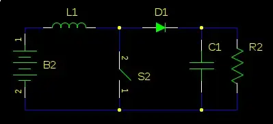
My simple sketch solution is below. It's half wave rectified to provide the low power for the +/- 18 V supply, and then feeds a DC/DC converter module for the 5V regulated supply. Note capacitor sizing (probably underdone for the + rail) and polarity. In terms of the transformer, get a 25 VA 15 V one and you're good to go. "Module" could be any number of 20W DC/DC supplies, just make sure it can accept a high enough Vin.

schematic

simulate this circuit – Schematic created using CircuitLab

awjlogan
  • 7,879
  • 2
  • 29
  • 45
  • Hi Logan, Looks like you get where this is going and the circuit above starting to look more like I was expecting as I was realizing the 5v supply power was going to be a big issue. Now trick is to find a DC2DC that will fit the bill. When I drew up my schematic I wasn't thinking the 5v rail was the big power user. Somehow I knew tho that it wasn't going to be a simple deal. I'll see what I can come up with. If this can't work then it's back to trying to fix the old smps or MartinF found a ready made unit but the -/+ supply was only 15v but then I could just remove the 2nd regs and wire in. – Kevin Smith Aug 20 '18 at 14:37
  • Well this is interesting, I connected a 5v supply to the digital and ran ammeter inline and at 5.35v the digital jumps around between 370mA to about 390mA max. So my initial hunch that the 5v rail was not a big draw was right. The display lit up and all the function was there, could change patches and edit them. So if the 5v barely uses 1/2W and you figure the -/+ 18v shouldn't draw more than 1W, what the hell did they need a 20W smps for ? overkill ? it's rather puzzling. Well I could build my circuit and try, worst scenario is it won't give enough current and won't run, maybe blow a reg or 2 – Kevin Smith Aug 20 '18 at 15:17
  • @KevinSmith It's not impossible that the power supply is a generic across their range (cheaper in volume), so you may be in luck. Be aware that even at 500 mA, the design above is still dumping ~8 W in the 5V regulator; more manageable than 60 W, but still a lot. – awjlogan Aug 20 '18 at 15:20
  • So if I were to go with a 15vac xfrmr it would bring the power down for the 5v reg using that calculation for reg consumption. Like you were saying a 15 vac secondary would be enough to run the -/+18v supply and ease up on the 5v reg maybe not quite enough so then I was thinking a custom wound xfrmr to have another secondary for the 5v reg that is much lower vdc feed for 7815. Or some other way to bring down the DC output from the 2nd bridge. What ya think ? – Kevin Smith Aug 21 '18 at 00:25
  • When you referred to the design above .... was that mine or yours? I was assuming you meant my design but maybe you were referring to yours ... gotta clear that up. – Kevin Smith Aug 21 '18 at 00:32
  • I forgot to mention I have a variac (3 actually) which I can use to give me whatever AC I want to use to prototype this thing. So I could use 2 variacs for 2 different AC sources to run each set of regs and should be able to do the 5v supply without killing the 7815. Not sure if one exists but maybe there is a 5v reg that can do more than 1W ? In the same kind of package like the 1W 7815. – Kevin Smith Aug 21 '18 at 00:39
  • Did some number crunching using your formulae and if I use the min Vin for 5v reg I get 4W (using a reg I found @ Digikey can get one up to several amps output current) so current limits shouldn't be an issue. If dissipating heat is the main concern, big heatsink with a fan should do the trick. However, I don't think the current draw for the 5v reg is going to even get close to 1 watt. Next experiment will be to test the 18v rails and see what they draw. – Kevin Smith Aug 21 '18 at 06:03
  • @KevinSmith Well, I would still stick with an off the shelf SMPS 5V supply, and then use the transformer for the +/- 18V - trafos are heavy and expensive. You can wire the AC to the 5V supply input and to the transformer. Connect your grounds on the output side. If the digital side is drawing about 350 mA, you should aim for 3-4 W supply; that's doable with a linear supply (LM338, for example) if inefficient. – awjlogan Aug 21 '18 at 08:47
  • Hi Logan, I have been working on the PS again and was looking at your circuit you drew above. The +/-18v 1/2 wave, I was wondering why the - supply uses such a smaller value cap for ripple and why you thot the + filter cap might too small ? Also when U use mF is that milli ? I have never used or even seen milli used for a very very long time. It make sense tho cuz then my caps are lrge. I was wonderin if the feed for the 5v reg could come off the +18v output as well ? as the 5v amp draw was verified absolutely as 400mA max. About to try it using yer 1/2 wave as 1st stage then feed 5v frm 18 – Kevin Smith Sep 07 '18 at 08:14
  • Since I don't have your recommended values in singles, I am going for 2200uF for the -18 and 5400uF for +18. just don't have much around for the values you suggested. As asked in last cmmnt, want to know why minus 18 supply filter is so much smaller ? Wouldn't they be the same, balanced ? I've seen other designs where they are same. – Kevin Smith Sep 07 '18 at 08:28
  • Re-garding the 5v supply feeding from the 18 v supply ... might be a problem as my new design does not isolate the grounds for both supplies, digi vs analog. This may or may not be an issue only a real world test would tell. They did isolate the two supply grounds in the original smps but that may only have been due to the nature of smps noise issues. Tomorrow I will test the loading issues of both supplies and see if the common ground across them will cause noise issues. I made the circuit I spoke of using +18 to feed the 5v reg and it works but under load ? yet to be seen if it's gonna work. – Kevin Smith Sep 07 '18 at 10:28