1

What I've:-

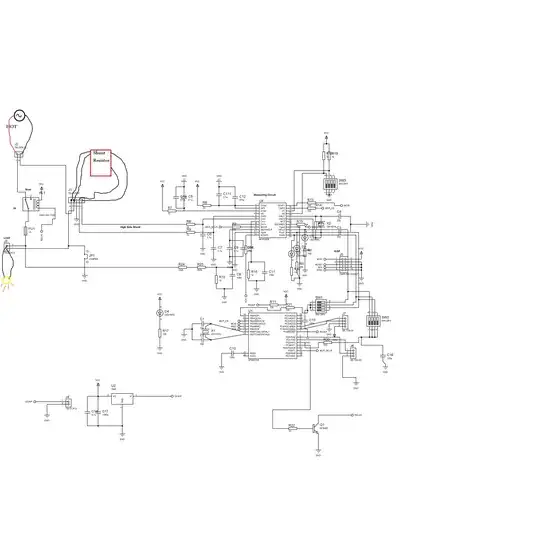
I'm using MCP3909 energy metering chip , I'm setting this chip in pulse output mode which gives output pulses proportional to the real power .

The used shunt resistor is 200 u Ohm .

Here's the full design:- enter image description here

What I did:

1- Fully testing the circuit --No connection errors

2- Applied AC input (220 V) with load (lamp ) -- worked

3- Applied DC input(5V -USB ) with load(LED) -- worked

4- Removed the MCU , to check if there's a programming error or something

Circuit behavior:

In all previous test LEDS (D1 -OFF ,D2 & D3 -ON ) respectively (HFOUT ,FOUT0 & FOUT1 )

My questions:

1- MCP initially works in Pulse output mode , right ? this means that LEDS should toggle in case of any load

2- Why there is very small voltage drop on the 200 u ohm shunt resistor ? I applied 4 A load on it ? but no pulses from MCP is out ?

3- Am I operating the MCP 3909 right in the pulse output Mode ?

4- Why FOUT0 & FOUT1 are always ON ?

5- I checked the Pin Input Ref in/Out , the voltage on it was 0.5 V , it has a 100 nf cap to ground

xsari3x
  • 1,608
  • 5
  • 27
  • 42
  • Your schematic is pretty unreadable :-( I think you will be more likely to get some answers if you [tidy it up a bit](http://electronics.stackexchange.com/questions/28251/rules-and-guidelines-for-drawing-good-schematics) and present the information as clearly as possible. – Oli Glaser Aug 30 '12 at 03:15
  • 200µΩ is very small, you may need a shunt with a greater resistance. – starblue Aug 30 '12 at 05:16
  • Yes, starblue has a good point regarding question 2 - 4A through 200uOhm is only 0.8mV. – Oli Glaser Aug 30 '12 at 06:11
  • The resistor is so small because the schematic is tiny :-) Actually, schematic image is quite high res, so open in separate window to see larger. – gwideman Mar 12 '13 at 22:20
  • Whoa, you're playing with electronics directly connected to the mains. You need to be careful, and know *exactly* what you're doing. – Connor Wolf Mar 13 '13 at 04:36

1 Answers1

2
  • The MCP3909 should always operate in pulse output mode by default. So the LEDs should toggle when the IC detects power
  • According to the data sheet (figure 1-1) Fout1/Fout0 create low-pulses and are active high, while HFout creates high-pulses
    • that's why the D2 and D3 are always on (Fout creates 275ms low-pulses, HFout creates 90ms high-pulses)
  • a 200 _micro_ohm current sense resistor is rather low for a 5A load. This results in a voltage drop of only 0.8mV. But the full scale voltage on the current channel is 440mV (see page 3) with a gain of 1

Lets calculate:

  • on the current channel, you get 1/500th of the full scale
  • on the voltage channel, you get 1/2 of the full scale
  • so the detected power is 1/1000 of the full scale
  • for Fout the frequency is, depending on the multiplier configuration, between 0.37 and 2.96 Hz for full power (when you are using a 3.58Mhz crystal as the data sheets suggests)
  • D2 and D3 toggle with 1/1000th of that - no wonder they are on always
  • HFout pulses, on full scale, with 27.1 or 47.42 Hz (depending on the configuration)
  • so with 1/1000th of that, you will get on small high-pulse every 25 of 50 seconds

So you should use a larger current sense resistor. For a load of 4A, about 100 _milli_ohm would be OK, then would be near full scale on the current channel.

Regarding the 0.5V you measure for the voltage reference: is this with the MCU attached? It should be 2.4V - maybe you have a short (or an unclean solder joint) there?

hli
  • 2,336
  • 15
  • 17