5

Hey Electrical Engineers,

I'm a newbie to electrical engineering (I am a software developer by trade and am starting to work with Raspberry Pis and want to learn about basic circuit design).

My first project involves converting an LED traffic light for indoor use. The lights in the unit I have purchased have 230VAC FuturLED made by Swarco. According to the data sheet -- https://www.swarco.com/futurit-en/Products/Signals/LED-Modules/FUTURLED3-230V-AC the LEDs can operate at full brightness on 196 – 253 VAC, and at a dimmed brightness at 150 V – 170 VAC.

Because I'm a resident of North America, I will be working with standard ~110VAC household power. I could easily step up the voltage from 110 to 220VAC with a cheap off-the-shelf voltage converter, but if I want to operate in "dim mode" I need to either step up from 110 to ~160VAC or step down from 220VAC to ~160VAC (after stepping up from 110VAC).

The wattage of these LEDs is 12W each at full brightness, and 8W at dimmed brightness.

My questions are:

1) I am having trouble finding a step-up/step-down transformer that will output ~160VAC. Do such things exist, or would I need to have one custom built (sounds expensive)?

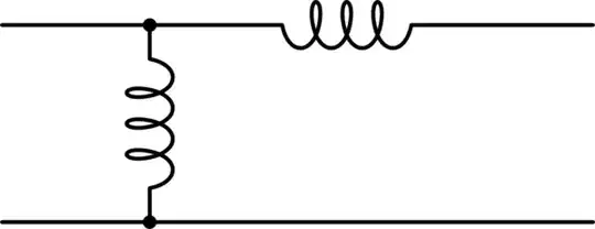
2) I've read that I can use 2 resistors to "split" the voltage and yield 160 volts, but can this be done with AC? I can't find a conclusive answer in my research, but I'm beginning to think resistors only work with DC current.

3) Is there another approach?

Michael Karas
  • 56,889
  • 3
  • 70
  • 138
andrewniesen
  • 167
  • 1
  • 2
  • 5
    While expensive to buy just for this, if you can find a surplus `variac` that could be quite useful to confirm how you would actually like to operate this. – Chris Stratton Aug 13 '18 at 14:32
  • 1
    You can put gray-tinted clear plastic over the LEDs to simulate dim mode. – Andrew Morton Aug 13 '18 at 18:20
  • Have you considered using a garden-variety light dimmer? Might need to use an RC (or maybe LC) filter, if the lamp demands sinusoidal input, but should be no big deal. – Hot Licks Aug 14 '18 at 01:30
  • 2
    I just want to caution you that these kind of voltages can be dangerous. Your first statement about "working with Raspberry Pis to learn basic circuit design" is a good one, but to me that implies learning with lower and safer voltages before moving on. "I've read that I can use 2 resistors to "split" the voltage and yield 160 volts" Yep, you can do that, and two resistors in series is about as basic as circuit design gets, and is important to understand. You might want to start with something a little less deadly. Just my advice... – Steve Aug 14 '18 at 03:26
  • Just FYI: "Normal" North American household service is 240/120. This is 2 phases of 120VAC, which are 180deg out of phase with each other, giving 240VAC between the phases (each phase is 120VAC to neutral/ground). Thus, it's highly likely that your house already has 240VAC available (exact voltage will vary, somewhat). However, to get this voltage you would likely need to run a special circuit from your breaker box. Thus, you are probably better off designing to use the 120VAC which you will get from a "normal" outlet, as it appears you are already targeting. – Makyen Aug 14 '18 at 04:02
  • When the manufacturer offers also 110v versions it might be as easy as changing a jumper wire to reconfigure the PSU – PlasmaHH Aug 14 '18 at 06:40
  • This is about the hundredth time I've seen someone trying to use 1) 2) 3) instead of valid markdown. Maybe it's time to either get a bot to warn posters, or to modify the markdown to accept it. – pipe Aug 14 '18 at 06:51
  • 1
    "but I'm beginning to think resistors only work with DC current" I'm going to be blunt here: if that's the level of understanding you have about electronics, you *should not* be doing what you intend to before you get a clue what things like voltage, current, resistance and isolation actually are. Such voltages are dangerous, especially if you don't know what you're doing. – Mast Aug 14 '18 at 11:25

10 Answers10

9

1) Indeed a suitable transformer to make the 160 VAC will be hard to find. And because almost no one needs 160 VAC it will be expensive. If you were not a newbee in EE I could suggest a 120 V to 40 V transformer and then connecting the secondary in series with AC mains but that needs you to be aware of the dangers of doing this so I didn't suggest this.

2) Yes using a resistor divider to make 160 V AC from 240 V AC can be done, resistors don't know the difference between AC and DC. But again that is not power efficient and partly defeats the use of power efficient LED lights.

The actual circuit in the LED lamps also matters, some circuits simply output the same light level whatever the input voltage (within practical limits obviously).

3a) Try if the lights just work on 120 VAC, you could be lucky.

3b) Buy lights that are suitable for 120 VAC, in the end that could end up cheaper than a custom transformer.

Bimpelrekkie
  • 80,139
  • 2
  • 93
  • 183
6

I can suggest two approaches:

  1. You may be able to purchase a 1:1 isolation transformer that is rated at the current level that you need and then remove some of the turns from one of the windings.

    This would have to be done very carefully to maintain the insulation integrity of the high voltage transformer and would only really be applicable for a one-off project. This could be done to support creating a step up transformer from 120 to 160VAC or a step down from 230 to 160VAC.

  2. Investigate whether this LED lamp capable of supporting being dimmed by a standard 230VAC dimmer switch. If so you could connect the light to a 230V circuit and then set the dimmer to the light level that you want.

Michael Karas
  • 56,889
  • 3
  • 70
  • 138
  • option 1 sounds interesting - is there any formula for the number of turns that would have to be removed? – andrewniesen Aug 13 '18 at 15:23
  • You would need to know the number of turns that were in each winding to start with. For a 1::1 transformer the number of turns in both windings are the same. The voltage ratio across the transformer is related to the turns ratio. Since you would probably not know the actual ratios of a particular transformer it can be tricky....especially if you have to remove the laminations from the transformer to get it apart to change its windings. In past when I've done this I just removed the whole secondary winding which is usually the outer one and counted all its turns. Then re-wound back accordingly. – Michael Karas Aug 13 '18 at 15:33
  • 1
    I would have to say that modifying the transformer is impractical, unless you manage to find a 60-year-old transformer that is take-apart-able. – Hot Licks Aug 14 '18 at 01:31
  • If modding a existing transformer you could measure the DC resistance of the secondary, remove some (e.g. 10) turns, measure again, then ratio to find the number of turns. You might need quite a sensitive meter if the wire isn't very thin – Chris H Aug 14 '18 at 09:15
  • @ChrisH - I have actually tried that in the past when trying to "adjust" a transformer. It did not work very well with the meters that I had at my disposal. It would require a rather expensive meter that was well calibrated. But yes the idea is good in theory. – Michael Karas Aug 14 '18 at 12:06
  • @MichaelKaras I have access to some rather good meters in work but I know what you mean, and would be much more likely to adjust tranformers at home, where I only have cheap meters – Chris H Aug 14 '18 at 12:07
4

There is no circuit schematic on the web page you linked but it seems that there are no active electronics in the lamps and that the LEDs are wired in some sort of series combination to run directly from the mains.

enter image description here

Figure 1. Phase-controlled triac dimmer waveform. By varying the turn-on point from 0° to 180° on each half-cycle the voltage can be reduced from 100% to 0%.

A standard domestic dimmer on your 220 V step-up transformer will produce this type of control and may suit your purposes. The dimmers are very efficient as during the "off" part of the cycle the current is zero so the power dissipated in the triac is zero. During the "on" part of the cycle about 1 V or so will be dropped across the triac so the power dissipated will be low. The standard heatsink on a domestic dimmer should be adequate for your purposes. A resistive solution would generate a fair bit of heat which may be problematic.

Watch the voltage rating of your dimmer. It will have to be ≥ 220 V rated so you might end up purchasing a European one.

Transistor
  • 168,990
  • 12
  • 186
  • 385
  • thanks for the advice - are you saying I could use standard 110V household dimmer in front of an electronic voltage converter (like this one https://www.amazon.com/Simran-SMF-100-Universal-Voltage-Converter/dp/B003DQSMGC/) would work? Or maybe an electronic dimmer? Or a conventional household dimmer in front of a magnetic transformer to step up the voltage? – andrewniesen Aug 13 '18 at 15:21
  • No, you can't use a dimmer in front of a voltage converter. The dimmer doesn't lower the voltage; it introduces some time where the voltage is zero, while the standard waveform isn't - see the rectangular cutouts in the above diagram. These cutouts cause nasty stuff to happen in step-up transformers. Best thing you can do is get a 110->220V converter, then a 220V dimmer behind that. If you can't find those on amazon.com, try amazon.co.uk for a shop that has euro parts but without the language barrier. – Guntram Blohm Aug 13 '18 at 20:57
2

You will struggle to find a 120 -> 160 VAC or 240 -> 160 VAC transformer as there aren't a huge number of use cases.

You should be able to find a suitable variac, which you would be able to set to an appropriate output voltage. This would be able to function as a dimmer also.

Colin
  • 4,499
  • 2
  • 19
  • 33
2

You can buy a Hammond 290HX which has 120:356CT windings. You can use half the 356V winding to get 178V @420mA, and buck that down to 171V using the 6.4V CT winding.

Cyan wires are the output.

enter image description here

Spehro Pefhany
  • 376,485
  • 21
  • 320
  • 842
1

For dimming, the best approach is likely an electronic dimmer. Feeding an electronic dimmer with an electronic voltage converter or vice-versa may be problematic. I would consider a conventional transformer or autotransformer for the 120:240 voltage conversion. An electronic dimmer could probably be used on either the 120 V side or the 240 V side of that.

  • So if I use a "conventional" (I assume magnetic) transformer like this one - https://www.mouser.com/datasheet/2/177/EDB290WX-245431.pdf - it will play nicely with a 220-240VAC european dimmer -- like this one -- https://www.amazon.de/Viribright-Dimmer-220V-200WATT-Helligkeitsregler/dp/B00APEK0TM -- to achieve the 160VAC needed for the "dim mode"? – andrewniesen Aug 13 '18 at 15:15
  • or maybe a Home Depot lighting dimmer on the 120VAC side of the transformer? – andrewniesen Aug 13 '18 at 15:22
  • For two lights at 12W each, you need a transformer rated at least 24VA. The one you linked has 237V winding rated 237V x .05A = 18.9VA. The dimmer looks fine. It is marked as being suitable for LEDs. You should check if your LEDs describe any limitations for dimmers. A dimmer for the 120V side would need to have AC phase back output as illustrated by @Transistor and should be used with a transformer that is a bit larger because of additional heating. –  Aug 13 '18 at 15:49
  • I don't know why I assumed 2 lights or that two would be on at the same time. For just one light at a time 18.9 VA is fine. Also the spec says 45-55 Hz. That seems strange and could be a problem. –  Aug 13 '18 at 16:03
0

1) I bet you won't find any, as there are no popular applications for 160V. BUT - you can find a variable transformer, usually of autotransformer kind (variac) that can be simply dialed to the voltage you need.

2) Resistors don't care, they work on AC just as well as on DC. But voltage divider wastes a lot of power. It's not just about wasting power being pointless with highly efficient LEDs. When we're talking about mains levels of power it means that this "mere inefficiency" can turn out to be so big that the resistors will cook off and explode. Plus, it's ridiculously difficult to control, because the voltage changes as you connect/disconnect things. Bottom line: don't do it, it only works reasonably well for controlling minuscule currents.

3) There are many other approaches but frankly, in your case only the variac approach sounds feasible. Eg: you could try a triac dimmer, but LEDs are usually dimmer-incompatible unless stated otherwise (their capacitor-fed power supplies take peak voltage anyway, so dimmer does nothing).

So: start looking for a variac of appropriate size (no smaller than 12W and larger about 2 times, not 100 times). They're usually quite expensive because of all the copper, but they just work. Only remember to watch the dial setting, if you set it to 100%, the output will be 220V and your LEDs probably won't survive. Try it out on a ~12W 220V incandescent bulb first (or two 110V bulbs connected in series), to understand how it works. Generally I recommend you to work on cheap bulbs of similar wattage and move to LEDs only when satisfied with your dimmer/controller.

Caveat: Most American houses do have 220V access, they're just called "dryer socket" or "boiler socket" and used, as the name implies, for the largest loads in the house. If you can access such socket, you don't need a cheap step up. On the other hand, you might find a variac that does the stepping up or can work in step up mode, that's also worth looking at.

Agent_L
  • 1,725
  • 10
  • 14
  • 1
    Though keep in mind that the USA 220V outlets are typically used for high-current appliances (stove, dryer, water heater, etc.) and any non high-current device should probably be used with a secondary current limiter (fuse, circuit breaker) after the wall plug to limit damage and personal peril if your device decides to short out. – Milwrdfan Aug 13 '18 at 19:23
0

schematic

simulate this circuit – Schematic created using CircuitLab You don't need a 240 to 160 transformer to get the dimming voltage. You can use a 240 to 80 with the secondary connected to buck the primary. The schematic shows a buck (or boost) connection which (adds or) subtracts the secondary voltage (to or) from the primary voltage. Swapping the secondary leads can change it from buck to boost. You might have as much trouble finding 240 to 80 as 240 to 160, but it's another option.

0

LED's of course don't work on AC, but there's probably a diode bridge rectifier included. That's a pointer to the redneck dimming approach: throwing away one half of the cycle can be done with a single diode and will effectively dim the LED to about 6W. Most people won't detect the 60 Hz flicker.

Remember that the diode has to handle peak voltages, so about 400V peak for 220V AC. And it's good engineering to also choose a diode that can handle the peak current, which is going to be approximately 0.01A.

Just to confirm: This means you're not working with 160VAC at all. You're using either +220/-220V for full power or +220V/0V for dimmed.

MSalters
  • 561
  • 3
  • 7
-2

Why not just invest $12 bucks in a blank transformer core, $5 for a spool of magnet wire and and wind it yourself?

https://www.ebay.com/itm/1set-PC40-E55-EE55B-11-11pins-Ferrite-Cores-bobbin-transformer-core-/151826270910

KD Mann
  • 78
  • 1
  • Or better yet (since LEDs always run on DC anyway) rip out the AC-DC conversion "guts" from these units and power them from DC directly. Any 5v power supply of sufficient amperage (with an appropriate sized current limiting resistor) should light up these LEDs just fine. – KD Mann Aug 13 '18 at 19:05
  • Here's a decent video on DIY transformer construction... https://www.youtube.com/watch?v=s6NyTprQCBI – KD Mann Aug 13 '18 at 19:12
  • 5
    "Wind a high-voltage transformer yourself" is not something I'd recommend to someone who describes themselves as a newbie in EE. – Guntram Blohm Aug 13 '18 at 21:03