0

Follow on from : earlier post

Below is an LTSpice simulation of an MC34063 step up (5v to 9v) circuit. As you can see, this particular circuit is working correctly, and delivering about 300mA.

enter image description here

The N-Channel FET used is rated at 6A continuous Raising the load to about 500mA the circuit still just manages 9V, but at 1A I get this :

enter image description here

The inductor I'm using is rated at 15A. What is stopping the circuit from delivering 1A at 9V?

below is the waveform waveform Green - output voltage Blue - voltage source/drain

Richard
  • 289
  • 1
  • 11
  • What does your gate drive and Vds look like? – Spehro Pefhany Aug 06 '18 at 16:15
  • 2
    Have you done any calculations? Play with this http://schmidt-walter-schaltnetzteile.de/smps_e/aww_smps_e.html and notice the peak current. Also, your lower PNP transistor is connected backward. The emitters should be connected together. Also why you do not use a modern and "real PWM" controller. MC34063 is not a "real" PWM controller. – G36 Aug 06 '18 at 16:25
  • Also is your MOSFET a logic-level type MOSFET? – G36 Aug 06 '18 at 16:39
  • Lolz. Yes.. PNP is upside down... Correcting.. Will see what happens.. – Richard Aug 06 '18 at 16:53
  • @G36 Corrected PNP.. Push Pull seems to offer no real benefit over just switching the FET with a single NPN transistor. Maybe slightly faster pull to GND etc? I'm using the MC34063 because I have a bag of them and they cost next to nothing... The final circuit I might publish, and it will probably be cheap enough for people to make themselves. – Richard Aug 06 '18 at 16:58
  • @SpehroPefhany Please can you elaborate. When you say Vds do you mean measure the voltage at the supply? And by gate you mean measure the voltage at the FET gate? (the junction of the BJT pair)? – Richard Aug 06 '18 at 16:59
  • Where did you find the LTspice mode for MC34063? – G36 Aug 06 '18 at 17:07
  • And I suspect that your main problem here is that the MC34063 output is not able to give high enough voltage to fully open the MOSFET at 1A load current. – G36 Aug 06 '18 at 17:20
  • To confirm this plot the VDS voltage – G36 Aug 06 '18 at 17:23
  • Voltage between drain and source and voltage between gate and source. – Spehro Pefhany Aug 06 '18 at 17:28
  • @G36 See the post linked at the top of this post which I edited earlier today to contain the models. – Richard Aug 07 '18 at 09:59
  • @SpehroPefhany Site won't let me upload another image. Voltage between drain and source is between 3.5 and 6V, and voltage between gate and source is between 0.5v and 2.4v – Richard Aug 07 '18 at 11:56
  • After you reverse the pnp, the emitter will be at 0.7V, and the mosfet Vgs is also 0.7V. Is the mosfet switching properly? – Indraneel May 22 '21 at 06:17

3 Answers3

1

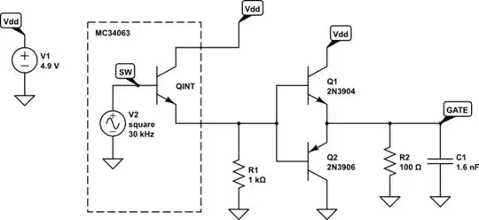
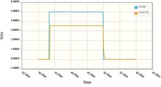
Here's a CircuitLab model of the output stage of the MC34063, driving the push-pull pair of transistors you have implemented. The 1.6nF capacitor represents (somewhat simplistically, I admit) the input capacitance of the MOSFET. The simulation shows that the output cannot drop below 0.6V or so, which is not surprising for an emitter follower configuration:

schematic

simulate this circuit – Schematic created using CircuitLab

enter image description here

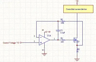
I believe your MOSFET is not switching completely off. That particular model, the IRF7401 (datasheet), has an unusually low \$V_{GS(TH)}\$, meaning that you'll need an unusually low gate voltage to switch it off, and I don't think 0.6V is low enough.

The gate voltage is certainly slewing fast enough, though, and the high of 3.7V is more than enough to switch it on, as can be seen in figures 1 and 3 of the datasheet.

The obvious solution would be to use a MOSFET with a larger gate-source threshold voltage, but that seems more of a hack than a solution. Ideally you want the gate voltage to drop further. One thing to try is give the bottom transistor a helping hand, with a resistor R2:

schematic

simulate this circuit

enter image description here

The downside to that idea is the wasted power in R2, due to the 50mA pulses (in the case where R2 is 100Ω).

It's all I have for a quick fix, that I can think of right now, but you should give it a whirl, and see if it helps. At the very least, you should be able to see if the problem really is due to an insufficiently low \$V_{GS}\$.

Simon Fitch
  • 27,759
  • 2
  • 16
  • 87
0

Apart from the problem of the PNP transistor being upside down (which I believe you have corrected), you might find that the newly corrected PNP will not switch off fast enough to deliver a decent square wave to the gate of the MOSFET. The input capacitance to the MOSFET (between gate and source) is 1.6 nF and this needs discharging probably a lot quicker than the circuit you have implemented.

If you look at the gate threshold voltage in the data sheet you will notice that it is 0.7 volts (quite low) and the MOSFET will not properly turn off until below that voltage. I suspect that trying to discharge the gate capacitor's voltage to that low level is the problem.

Andy aka
  • 434,556
  • 28
  • 351
  • 777
  • I thought that's what the push-pull does, it helps to pull the gate of the fet up and down faster? I've tried this with a resistor between the gate and ground, and that doesn't seem to improve anything? Do you have any suggestions? – Richard Aug 07 '18 at 11:58
  • You should confirm that the AC ripple on the 9 volts is a significantly lower frequency than your reference design in your previous question. A lower frequency means higher Vp-p ripple. What is the lowest voltage that could be made by the PNP transistor when operating in push-pull; you consider the base-emitter as a conducting diode with the base at 0 volts hence, the emitter cannot be lower than 0.7 volts or the PNP will not be discharging the gate. Given that the gate threshold voltage is so low, it's likely that the MOSFET is cycling between ON and lightly-ON and not ON-OFF. – Andy aka Aug 07 '18 at 12:04
0

Your peak MOSFET current is likely supposed to be in the 10A+ region and your drive voltage is pretty light (2.4V you say vs. the 4.5V the MOSFET would like to see). If that was the only problem you could replace the MOSFET with one that will operate from 1.8V drive, but that will make the problem Andy noted much worse.

There are three Vbe drops between the 5V supply and the MOSFET gate.

Sounds like it might be (depending on the waveform) turning off barely well enough for that particular MOSFET , but keep Andy's warning in mind and note that MOSFET Vgs(th) drops with increasing temperature. A low value resistor from gate to source should improve the minimum voltage.

You're above the optimal operating frequency for that poor old SMPS chip, so you are probably seeing some pretty ugly waveforms (meaning poor efficiency).

Also make sure the inductor rated saturation current (not carrying current) is high enough. 15A sounds about okay even if the efficiency is horrible.

Spehro Pefhany
  • 376,485
  • 21
  • 320
  • 842
  • I've dropped the frequency to 40Khz. That has made a small improvement but it's still not fixing the overall issue, which I think you're saying is that I'm not saturating the FET because the gate voltage is insufficient. And the waveform is not 'square' enough? – Richard Aug 07 '18 at 12:34
  • If you drop the frequency you have to increase the inductor value or the peak current will increase commensurate with the drop in frequency. I can't see the waveform so..? – Spehro Pefhany Aug 07 '18 at 12:36
  • StackExchange is not letting me upload images, so I've had to resort to drastic measures. Please see waveform in edits above (bottom of post) – Richard Aug 07 '18 at 14:13
  • This is with a 68uH inductor and a lower frequency. Asking for 1A at the output. – Richard Aug 07 '18 at 15:09