This is an intentionally very open ended question. What does it mean for an antenna to be a 50-ohm antenna at some frequency? How do you make a 50-ohm antenna for say 433.92MHz? What are the options? What are the consequences of it being different from 50-ohms?
Asked
Active
Viewed 2.9k times
8 Answers
15
What does it mean for an antenna to be a 50-ohm antenna at some frequency?
It means that if you apply 1 VRMS sine wave of that frequency at the end of the antenna, a 1/50 ARMS current will flow in the antenna at that point. V = IR
endolith
- 28,494
- 23
- 117
- 181
-
2Exactly. This can be generalized to the statement that the ratio of RMS voltage to current at any point on the antenna is 50, and the unit is, of course, ohms. – Kevin Vermeer Aug 05 '10 at 20:07
-
2So how do you build one for a target impedence? What's the design process? – vicatcu Aug 05 '10 at 21:20
-
2Also presumably imperfections come into play and you have to "tune" the circuit to the antenna (something like that), is there a clear approach to doing that? – vicatcu Aug 05 '10 at 21:21
-
Radio amateurs use VSWR meters to check and tune antennas. – Leon Heller Aug 05 '10 at 22:58
-
The antenna's impedance should match the connector's impedance should match the line's impedance should match the transmitter's impedance. Then there's no reflections. – endolith Aug 06 '10 at 00:59
-
2If you don't use some kind of antenna tuner (L-C network, usually,) it is almost always required to do some cut-and-try trimming. There are all sorts of rule-of-thumb equations out there, but the best advice is to cut your (I'm assuming prototype) antenna a bit too long and test it with a meter that can measure forward and reflected power. Trim, then test again. You want to trim for minimum reflected power, which will mean that your power is being radiated instead of reflected back into the amplifier finals and heating them up. – Jesse Aug 06 '10 at 07:13
11
When referring to RF equipment you have to deal with 'characteristic impedance', which is a property of antennas, feed lines, and even transmitter output stages.
The important thing is to make sure that impedances are matched up all the way from the equipment to the antenna. This is more important for transmitters, since more power is involved, but doesn't hurt for receivers either.
One thing you don't want to do is just wire together two items with different impedances. There are RF transformers of various kinds can be used to match up sections that otherwise would be mismatched. Any abrupt change in impedance causes RF energy encountering the mismatch to partially reflect, sort of like what happens when light strikes a piece of glass. When one end of the system is a 100W transmitter, this can result in significant energy being reflected back to the tranmitter's output stage. Basically, it's just inefficient, since the reflected energy just becomes waste heat in the transmitter, and the output from the antenna is diminished. The measure of how much reflection is going on is referred to as the standing wave ratio, often abbreviated SWR.
Not all RF systems are 50 ohms. There are kinds of coax (e.g. RG-59) that are 75 ohms, and 300 ohm twin lead that are not uncommon.
JustJeff
- 19,163
- 3
- 48
- 75
8
Trying to think what 433 is used for off the top of my head :) Is that the weak signals band?
At any rate, most 2-way radios are made to match up to a 50ohm antenna and the matching is left up to you. You can get an antenna that is already tuned, or you can do impedence matching through a number of techniques (see the referenced article below).
With a good match, you reduce standing waves. Standing waves build up when the radio sends out a nicely modulated signal but the antenna isn't resonating at that frequency and causes standing waves, which feed right back into the radio and can blow out the final stage.
The higher the output power, the more this becomes important. At very low power, say <1watt, the worst you have to worry about is the antenna not resonating and your signal not going anywhere. At higher powers, say 50+ watts, you can damage your transmitter in less than 1 second. Modern radios have built-in SWR detectors that will cut the power if it detects a problem. Those aren't always guaranteed to work though.
Brad Hein
- 1,042
- 3
- 13
- 18
-
3Unless this is a shared frequency band (such as ISM), I'm pretty sure this lies within a Ham band. In which case you have to take the test to transmit in the band. The test covers these questions. – Brad Hein Aug 05 '10 at 18:25
-
5KC2QLW ;) 433.92Mhz is actually the center frequency of an ISM band, not part of the Ham spectrum, and is goverend by Part 18 of the FCC rules. – vicatcu Aug 05 '10 at 19:57
-
1It's part of the UK 70 cms amateur band allocation. People have been unable to get into their cars after parking them close to a 70 cms amateur radio transmitter. – Leon Heller Aug 05 '10 at 22:10
-
2@vicatcu - (I appreciate this is an old thread, but your comment needs comment...) whilst 433.92Mhz is an ISM frequency, it is also a 70cm amateur frequency **world wide**. Use of the frequency for ISM is subject to not causing interference to hams, but you may suffer from hams using it! See also Leons comment! – Andrew Oct 26 '12 at 19:21
-
@Andrew sure, but you don't need a license to transmit on it (in most countries) was my main point. Thanks for the clarification though. – vicatcu Oct 28 '12 at 15:20
-
@vicatcu - agreed, subject to very strict criteria (eg in the EU its a max 100mW on 433MHz) – Andrew Oct 28 '12 at 15:49
6
A great tutorial: The Dropout’s Guide to PCB Trace Antenna Design
PeterJ
- 17,131
- 37
- 56
- 91
Daniel Grillo
- 7,659
- 18
- 51
- 69
4
It's also useful to understand why a 50-ohm antenna is so important.
Let's say you have a source with an output impedance (resistance) of 50 ohms, like the ideal battery/resistor combination in the following diagram:
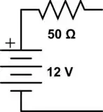
If you want to extract maximum power from the above source, the load resistor you need has to be 50 ohms. Try it yourself - put in 40, 50, and 60 ohms, and calculate how much power goes to the load in each case.
So, this is the reason why 50 ohm antennas are important: The sources that drive them typically have 50 ohms of impedance.
Therefore, if you want to deliver the most RF power from your 50-ohm source to your antenna - voila, only a 50 ohm antenna will do that!
neonzeon
- 1,810
- 11
- 14
-
Back to basics is good! I've never been able to think of a good explanation when *the application is a receiver*. Do you know of any explanations that start with a wave incident on an antenna, and still work? I've never seen it done. – uhoh Apr 17 '17 at 13:45
-
1One [reasonable speculation](https://www.microwaves101.com/encyclopedias/why-fifty-ohms#bottom-inside) is that 50 Ohm impedance was a good compromise between **power handling** and **low loss** for **air-dielectric** coaxial feed line. – neonzeon Apr 18 '17 at 20:35
-
Oh! microwaves101! I was looking for this site a while ago, and could not remember what it was called. I'd read some interesting things about skin depth at 60Hz a while ago while riding a bus, and later could not remember what or where. Excellent, thanks! – uhoh Apr 18 '17 at 20:38
4
A 1/4 wave antenna with four 1/4 wave radials at 45 degrees will give something close to 50 ohms impedance.
Leon Heller
- 38,774
- 2
- 60
- 96
-
This is very useful. I am not an electrical engineer, and therefore would am very interested in heuristics like this. Please add more if you know of any. – Dirk Aug 06 '10 at 01:12
-
3It's not really a heuristic, it can be predicted from basic electromagnetic theory. Something similar is the impedance of a folded half-wave dipole - 300 ohms. – Leon Heller Aug 06 '10 at 04:29
-
2Another example is the 30 ohms impedance of a 1/4 wave vertical over a ground plane. – Leon Heller Aug 06 '10 at 04:32
-
A microstrip line with standard FR4 PCB material will be about 0.1" wide. – Leon Heller Aug 06 '10 at 16:18
-
1A [dipole with bent/drop legs](http://www.comportco.com/~w5alt/antennas/notes/ant-notes.php?pg=16) can easily be made to 50 ohms. – neonzeon Dec 07 '16 at 13:57
-
This should be the selected answer as it is the only one that actually answers the OPs question. Antenna geometry is the key. – KalleMP May 22 '17 at 20:52
3
Here's a good app note for making a Bluetooth PCB antenna (2.4Ghz)
http://www.national.com/appinfo/cp3000/files/SBK/Bluetooth_Antenna_Design.pdf
Toby Jaffey
- 28,796
- 19
- 96
- 150
0
50 Ohm is input impedance of feedline to the antenna. In general practice, we connect an antenna with 50 Ohm connector ( like SMA, Coax...) so feedline impedance should be also 50 Ohm.
For Bluetooth antenna design at 2.4 GHz, you can also refer https://anilkrpandey.wordpress.com/2017/01/19/inverted-f-bluetooth-antenna-design-for-smart-phone/
Anil Pandey
- 102
- 2
- 10