27

It's said that electrolytic capacitors behave as inductors at high frequencies, which is why we put small ceramic caps in parallel with them:

Electrolytic, paper, or plastic film capacitors are a poor choice for decoupling at high frequencies; they basically consist of two sheets of metal foil separated by sheets of plastic or paper dielectric and formed into a roll. This kind of structure has considerable self inductance and acts more like an inductor than a capacitor at frequencies exceeding just a few MHz.

Impedance vs frequency curves for 100 pF, 1000 pF, 0.01 μF, 0.1 μF, 2.2 μF capacitors

Capacitor impedance vs. frequency.

Yet I also see a few things like this:

The "inductance problem" associated with electros is another idiotic myth - they have no more inductance than a length of wire the same as the length of the cap.

or

A popular myth is that electros have considerable inductance because of the way the foil is wound inside the can. This is nonsense - the foils are usually joined at the ends in the much the same way as with film caps. High frequency performance usually extends to several MHz, even with standard off-the-shelf electros and bipolar (non-polarised electrolytic) caps.

What is the exact nature of this effect and in what applications and frequencies do we need to worry about it? What are the practical implications?

endolith
  • 28,494
  • 23
  • 117
  • 181
  • 2
    I wonder what causes the curves to plunge steeper right before the upswing? Especially the green curve right above 10MHz. – DarenW Oct 15 '10 at 15:44
  • 2
    Resonance, I would assume. – endolith Oct 15 '10 at 16:06
  • 2
    You are citing the chart from ADI article, where they ment lytic caps being tantalum. There is no roll inside tantalum cap. –  Jul 20 '11 at 23:19
  • @Rocket Surgeon: There is no water inside tantalum cap either :) – endolith Jul 21 '11 at 00:43
  • You dont need complete mobility for polarized groups of molecules of conductor part of plate to have phase lag in GHz. They put colloidal graphite, silver and some organics into dry tantalums, which is not pure "electron gas" like in normal metal. But this discussion about solid chemistry will drive us way off topic. –  Jul 21 '11 at 02:02
  • Oh I get it: "Forget myths of winding inductance. These are spread by folks who subsequently want to sell so-called low inductive capacitors. Truth is, modern film capacitors have metal-sprayed end contacts that connect across the entire roll of film. Film caps are exactly as inductive as a solid copper cylinder of the same size." http://www.hypex.nl/docs/papers/AES124BP.pdf – endolith Jan 22 '13 at 20:21

6 Answers6

31

This effect is due to the effects of parasitic characteristics of the device. A capacitor has four basic parasitics:

Equivalent Series Resistance - ESR:

A capacitor is really a capacitor in series with the resistances of its leads, the foil in the dielectric, and other small resistances. This means that the capacitor cannot truly discharge instantly, and also that it will heat up when repeatedly charged and discharged. This is an important parameter when designing power systems.

Leakage current:

The dielectric is not ideal, so you can add a resistance in parallel with your capacitor. This is important in backup systems, and the leakage current of an electrolytic can be much greater than the current required to maintain RAM on a microcontroller.

Dielectric Absorption - CDA:

This is usually of less interest than the other parameters, especially for electrolytics, for which leakage current overwhelms the effect. For large ceramics, you can imagine that there is an RC circuit in parallel with the capacitor. When the capacitor is charged for a long period of time, the imagined capacitor acquires a charge. If the capacitor is rapidly discharged for a brief period and subsequently returned to an open circuit, the parasitic capacitor begins to recharge the main capacitor.

Equivalent Series Inductance - ESL:

By now, you shouldn't be too surprised that, if everything has capacitance as well as nonzero and non-infinite resistance, everything also has parasitic inductance. Whether these are significant is a function of frequency, which leads us to the topic of impedance.

We represent impedance by the letter Z. Impedance can be thought of like resistance, just in the frequency domain. In the same way that a resistance resists the flow of DC current, so does an impedance impede the flow of AC current. Just as resistance is V/R, if we integrate into the time domain, impedance is V(t)/ I(t).

You'll either have to do some calculus, or buy the following assertions about the impedance of a component with an applied sinusoidal voltage with a frequency of w:

\$ \begin{align} Z_{resistor} &= R\\ Z_{capacitor} &= \frac{1}{j \omega C} = \frac{1}{sC}\\ Z_{inductor} &= j\omega L = sL \end{align} \$

Yes, \$j\$ is the same as \$i\$ (the imaginary number, \$\sqrt{-1}\$), but in electronics, \$i\$ usually represents current, so we use \$j\$. Also, \$\omega\$ is traditionally the Greek letter omega (which looks like w.) The letter 's' refers to a complex frequency (not sinusoidal).

Yuck, right? But you get the idea - A resistor doesn't change its impedance when you apply an AC signal. A capacitor has reduced impedance with higher frequency, and it's nearly infinite at DC, which we expect. An inductor has increased impedance with higher frequency - think of an RF choke that's designed to remove spikes.

We can calculate the impedance of two components in series by adding the impedances. If we have a capacitor in series with an inductor, we have:

\$ \begin{align} Z &= Z_C + Z_L\\ &= \frac{1}{j\omega C + j\omega L} \end{align} \$

What happens when we increase the frequency? A long time ago, our component was an electrolytic capacitor, so we'll assume that \$C\$ is very much greater than \$L\$. At first glance, we'd imagine that the ratios wouldn't change. But, some trivial (Note: This is a relative term) complex algebra shows a different outcome:

\$ \begin{align*} Z &= \frac{1}{j \omega C} + j \omega L\\ &= \frac{1}{j \omega C} + \frac{j \omega L \times j \omega C}{j \omega C}\\ &= \frac{1 + j \omega L \times j \omega C)}{j \omega C}\\ &= \frac{1 - \omega^2 LC}{j \omega C}\\ &= \frac{-j \times (1 - \omega^2 LC)}{j \omega C}\\ &= \frac{(\omega^2 LC - 1) * j)}{\omega C} \end{align*} \$

Well, that was fun, right? This is the kind of thing you do once, remember the answer, and then don't worry about it. What do we know from the last equation? Consider first the case where \$\omega\$ is small, \$L\$ is small, and \$C\$ is large. We have, approximately,

\$ \begin{align*} \frac{(small * small * large - 1) \times j}{small * large} \end{align*} \$

which is a negative number (assuming \$small * small * large < 1\$, which it is for practical components). This is familiar as \$Z_C = \frac{-j}{\omega C}\$ - It's a capacitor!

How about, second, your case (High-frequency electrolytic) where \$\omega\$ is large, \$L\$ is small, and \$C\$ is large. We have, approximately,

\$ \begin{align*} \frac{(large * small * large - 1) \times j}{small * large} \end{align*} \$

which is a positive number (assuming \$large * small * large > 1\$). This is familiar as \$Z_L = j \omega L\$ - It's an inductor!

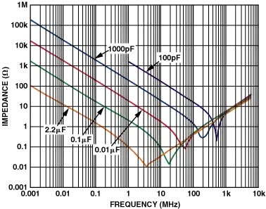
What happens if \$\omega^2 LC = 1\$? Then the impedance is zero!?!? Yes! This is called the resonant frequency - It's the point at the bottom of the curve you showed in your question. Why isn't it actually zero? Because of ESR.

TL,DR: Weird stuff happens when you increase the frequency a lot. Always follow the manufacturers' datasheets for decoupling your ICs, and get a good textbook or take a class if you need to do high speed stuff.

slurms
  • 247
  • 1
  • 3
  • 11
Kevin Vermeer
  • 19,989
  • 8
  • 57
  • 102
  • 2
    "Impedance can be thought of like resistance, just in the frequency domain." More accurately, resistance is a subset of impedance. Impedance is the combination of the resistance and reactance of a component or subcircuit. Maybe we should have a "What is impedance" question. :D – endolith Aug 05 '10 at 19:26
  • @Endolith - I agree, but only after several semesters of electrical theory do I understand your statement. While that would be the most pure route to an understanding of electricity, it's obscured by imaginary numbers and calculus. – Kevin Vermeer Aug 05 '10 at 20:16
  • Calculus is fun! But you really don't need to know that stuff to understand impedance. – endolith Aug 06 '10 at 00:25
  • 2
    epic response... – vicatcu Aug 06 '10 at 14:10
  • @Vicatu - I started off thinking, I'll just go over the basic parasitics, derive the impedance of a series LC circuit, and demonstrate that it's frequency dependent in such a way that the inductance becomes dominant at high frequency. Then, I started typing, and it just wouldn't finish itself. – Kevin Vermeer Aug 06 '10 at 14:34
  • 1
    imaginary numbers are just a tool to avoid differential equations amd integrals; they sort of make calculus into algebra :) – vicatcu Aug 06 '10 at 16:42
  • 1
    ...make calculus into **complex** algebra. Out of the frying pan and into the fire. – Kevin Vermeer Aug 06 '10 at 16:55
  • i wouldn't say your dodging calculus or diffEQ at all, they are used in the derivation of the impedance of these components at sinusoidal frequencies as well as in the derivation of the tools required for the transforms. I mean you could say that using a fourier transform is dodging integration by the same logic :) Its really euler's formula that makes this type of analysis possible. Its a pretty wacky relationship at first glance actually. – Mark Aug 06 '10 at 21:42
  • So everything acts as an inductor at high enough frequency? Is the inductance primarily from the coiled foil layers? – endolith Dec 02 '10 at 19:29
  • 2
    This is very old news, but how'd you get from \$Z_C+Z_L\$ to \$1/(j\omega{}C + j\omega{}L)\$? Shouldn't it be \$\frac{1}{j\omega{}C} + j\omega{}L\$? – The Photon Dec 17 '14 at 17:09
2

Question was not "if lytics are inductive", but why ? This is quite a puzzle, but comparison to ceramic caps plots for solid state chemistry can give a clue, that something is special for lytic caps only. So the question belongs to chemistry, not to electronics.

Increase of impedance after reaching minimum at high frequencies is caused by energy accumulated in form of rotating (or stretched/displaced) charged mass of large ions or polarized molecules. Each molecule in solution is acting like group of resonators (not just inductance) with sharp phase plot near several resonating frequencies.

There is interesting study about impedance measurement for pure water and metal ions in range of few MHz.

http://commons.emich.edu/cgi/viewcontent.cgi?article=1200&context=theses&sei-redir=1#search=%22ion%20solution%20impedance%20MHz%22

  • o_O Are you sure it's not just from the geometry of the caps? The plates rolled up in a spiral, etc. – endolith Jul 20 '11 at 20:42
  • 1
    Yes, I am sure. Consider plates, being two spirals, having exactly opposite currents and concentric, so both plate-coils are sharing the same magnetic field. I makes it an autotransformer 1:1 with very low leakage inductance (better than ordinary autotransformer even). I'd attribute may be 10% of effect to inductance, rest to ion inertia. –  Jul 20 '11 at 23:13
2

Anyone with access to an impedance meter (HP / Venable) can easily tell you that electrolytic capacitors certainly do become inductive at high frequencies.

This is part of the reason why you see a lot of ceramic capacitors used in high-frequency DC-DC converters - electrolytics simply aren't that good up in the hundreds of kilohertz / megahertz.

This is also why ceramic capacitors from 100nF - 1uF are commonly used as IC decouplers - an electrolytic cannot beat a small ceramic can because of its high-frequency impedance.

Adam Lawrence
  • 32,921
  • 3
  • 58
  • 110
1

The key is that these have the form of a roll, which is similar to a coil, i.e. the current flows in circles. This causes a relatively high inductance.

Other capacitors have the form of sheets (ceramic) or of two surfaces on a porous material (tantal, supercaps), so they don't show this effect.

starblue
  • 6,462
  • 2
  • 21
  • 35
  • I think that has very little to do with the issue. This is a problem even for electrolytics that have folded layers (See http://www.vishay.com/docs/28356/intro.pdf) – Kevin Vermeer Aug 05 '10 at 19:13
  • Everything has inductance, but coils have more inductance than folded layers, so the parasitic inductance will be larger, and the inductance of a coiled capacitor will take over at lower frequencies than one with folded layers? – endolith Aug 05 '10 at 19:32
  • 1
    @reemrevnivek Interesting document, though there are no hard numbers on ESL. They seem to use several tricks to reduce ESR and ESL, like connecting to all layers simultaneously on the side of the roll, or connecting to the middle of the roll, so that the magnetic fields cancel. – starblue Aug 06 '10 at 20:11
0

In aluminum electrolytics the foils are not joined the way film caps are. This has to make induction high. However, there are always specials, so who knows?

enter image description here

Robert Endl
  • 2,197
  • 11
  • 12
0

cool question - generally speaking a capacitor with capacitance C has an complex impedence with magnitude 1/(2*pi*f*C), fwiw. So at high frequencies a capacitor is supposed look like a short circuit (i.e. 0 ohms). I'm unfamiliar with the argument that they start to act like an inductor (which implies that at some point the impedence increases starts to increase with frequency, since an inductor of size L has a complex impedence with magnitude 2*pi*f*L... I guess I don't really buy it, but I have no basis for that.

vicatcu
  • 22,499
  • 13
  • 79
  • 155
  • Well, all components behave differently from their idealized versions in certain conditions. Real inductors have DC resistance while idealized inductors don't, for instance. – endolith Aug 05 '10 at 17:54
  • +1 for "I don't really buy it." I thought this for about the first three months of my analog circuit design class. Still do sometimes. *"Imaginary numbers? Get real!"* I should point out that I used the frequency in radians, while you used 2pi*f for the same purpose. – Kevin Vermeer Aug 05 '10 at 19:19
  • @reemrevnivek, sure and for those who don't know omega = 2*pi*f is a good conversion to know; where omega is the "angular frequency" specified in radians, and f is frequency measured in Hz. – vicatcu Aug 06 '10 at 14:10