3

schematic

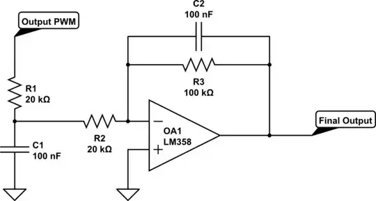
simulate this circuit – Schematic created using CircuitLab

I am using the PIC16F1786 in a current transducer to measure 0-1 Amp DC. I use an A/D converter to measure voltage from a Hall Effect and along with some software calculations use the Programmable Switch Mode Controller to produce a 12-bit PWM. Using that PWM to produce a final output of 0-5VDC.

I use software to calibrate two end points at 0 Amp DC input and 1 Amp DC input to create a y = mx + b equation to map my A/D readings from the Hall Effect to my PWM output.

Near my end points of calibration my final output is exactly where I expect it to be, however in between seems to exhibit some nonlinearities. I have double checked my mapping from A/D to PWM and it seems correct.

What I am seeing is, if using my two calibrated end points and I find the exact mid-point I would expect to see exactly (or pretty darn close) to half my Final Output. However, I am seeing between 20-25mV higher than I am expecting. Unfortunately this needs to be a high precision product and this is too large of an error.

Is there any known issues with PWMs being slightly non-linear? Everything from my oscilloscope readings tells me that it is a perfectly square waveform. Or perhaps my Final Output stage may be slightly off? All of my components are 1%, would it be worth trying to use 0.1% resistors?

Swinee16
  • 31
  • 3
  • I'd suspect the analog parts first. Have you considered offsets in the opamp? The 358 is far from the worst opamp you could use, but I don't think it is often used together with the words "high precision." – JRE Jul 26 '18 at 15:18
  • I have also experimented with the OPA2227 and had similar if not the same results as with the LM358. – Swinee16 Jul 26 '18 at 15:24
  • 1
    I think you should start by setting precise digital inputs to the PWM (forget the ADC) and see what you get from the analog output. Make measurements at 0/20/50/80/100%. That will tell you more than we can guess. Resistor tolerance basically has no effect on linearity, but saturation does and perhaps there are dynamic effects. You did not mention the op-amp supply rails and actual desired output voltage limits. That would be good to know. – Spehro Pefhany Jul 26 '18 at 15:42
  • INL and DNL of your ADC may acount for three LSB error. What is your 25 mV error in terms of peak full scale output and zero i.e. give absolute numbers because 25 mV means nothing. Also why are you using an op-amp gain of MINUS 5? – Andy aka Jul 26 '18 at 15:52
  • Sorry I didn't make this more clear in the original post, but using my software I set my PWM to specific digital values and that is what flagged my initial concern. I used the 2 calibrated points and gave my PWM specific values based on those (10%, 20%, 30% ... etc). Except for my end points everything in between was slightly higher than I expected, the worse at 50% around 20-25mV. – Swinee16 Jul 26 '18 at 15:54
  • Even though it is a 12 bit ADC, the differential characteristics list the resolution as 10 bits. Datasheet page 402. – Peter Smith Jul 26 '18 at 15:54
  • Hall sensor currents have hysteresis errors of this magnitude. Please check this article: https://www.allegromicro.com/en/Design-Center/Technical-Documents/Hall-Effect-Sensor-IC-Publications/Hysteresis-Mitigation-in-Current-Sensor-ICs-Using-Ferromagnetic-Cores.aspx – Dorian Jul 26 '18 at 15:59
  • @Dorian I have considered this a few weeks ago, and after some testing I felt like I was no where close to saturation. I did an XY plot using my Oscilloscope to produce a Hysteresis Loop and found that to be fine. I think my calculations put me right around 4 or 5 Gauss, so I am not worried that I'm close to saturating and that I might have a high remanence – Swinee16 Jul 26 '18 at 17:31
  • The output of LM358 is 0 to -15V ? – Dorian Jul 26 '18 at 17:49
  • I used a dual supply +12 and -12, since it needs to sense positive and negative directions. 5VDC (positive direction) and -5VDC (negative direction) – Swinee16 Jul 26 '18 at 17:58
  • So the PWM output is in +- 2.5V range or how do you obtain positive voltage at the output? – Dorian Jul 26 '18 at 18:02
  • Yes my reference voltages are +-2.5V, guess I should said this in my original post – Swinee16 Jul 26 '18 at 18:12
  • @Swinee16 S o how is the pwm output stage? To get my point the instantaneous output current (for 0 or 1) varies with the duty cycle due the variable voltage on C1. The V/I characteristic of PWM output might not be linear. Do you have a strong buffer with low impedance reported to R1 R2 and the precision expected? – Dorian Jul 26 '18 at 18:29
  • Oh, I see from your other comment. It might be this the source, I don't have access to the datasheet now. Another source might be the power supply for the PIC, have you checked that it stays 2.5V with mV error over all range of duty cycle? – Dorian Jul 26 '18 at 19:09
  • 1
    Andy had made a similar remark and I think you are both right, I think it has to do with a small change in the power supply. It does seem to slightly vary over the duty cycle – Swinee16 Jul 26 '18 at 20:29

1 Answers1

1

enter image description here

The INL and DNL error for your ADC could account for an error of 3 LSbs. Given that you might be using the 10 bit ADC, and may have (say) a reference span of 5 volts, the real voltage error could be as high as: -

3/1024 x 5 volts = 14.6 mV. Given that your op-amp has a gain of 5 this could be seen as a value as high as 73 mV.

If you are using the 12 bit ADC configuration then the data sheet for the PIC does not give maximum values for DNL and INL but, my estamate based on typical values would be about half of the 73 mV potential error.

What is ADC INL: -

enter image description here

It stands for Integral Non-linearity. DML is similar except it's more related to bit errors like this: -

enter image description here

picture source.

EDITED SECTION

Also, your PWM signal may be causing this error. It appears that your PWM output is bipolar in nature capable of highs of +2.5 volts and lows of -2.5 volts? If so then how good is the PIC at controlling the amplitude of those limits. That is to say, how matched are they as PWM voltage levels? Any duty cycle related changes in amplitude could be a big source of error.

I think you might have it Andy, I took a look and it looks like they vary just enough that it is causing problems. Which is leading me to believe my Vref+ and Vref- are not as constant as I thought.

Andy aka
  • 434,556
  • 28
  • 351
  • 777
  • I can see how this causes issues with my ADC,which I will definitely need to revisit. But if I disable my A/D and just assign fixed numerical values to my PWM Duty Cycle for testing purposes. I still see an issue. I am reading my "Final output" with a digital multimeter not with an A/D, I don't know if that was causing confusion, and my bad. The A/D is part of another part of my circuit which is not shown in my original post. The 25mV i was mentioning before is the difference between what I should theoretically be getting and what I actually am reading from my digital multimeter – Swinee16 Jul 26 '18 at 17:06
  • You said the ADC was measuring the Hall effect sensor and that the ADC result was defining the PWM mark space ratio yes? I’m unsure what the “other” circuit is and only assumed the signal string I’ve just stated. – Andy aka Jul 26 '18 at 17:57
  • Please also explain why you are using an inverting virtual earth amplifier and how you generate a PWM waveform that can produce a positive output voltage on the opamp output. This is next on the list because I smell problems of linearity here too. – Andy aka Jul 26 '18 at 18:03
  • You are correct, ADC measures hall sense and PWM is calculated from that value. So an INL or DNL error might cause the PWM calculation to be off, I get that, makes total sense. But say I give my PWM a constant value of 3000 and as a result I get a voltage of 5.00VDC from my Op amp circuitry, then a PWM value of 1000 which gives a 0.00 VDC from my Op amp. I would assume then a PWM value of 2000 would give 2.50 VDC. However I get 2.52 VDC, this is the type of problem I was getting – Swinee16 Jul 26 '18 at 18:07
  • To your second question, my PIC reference is a +2.5 and -2.5, total of 5V. That way I am able to produce both positive and negative values depending on the currents direction through a Hall Sensor. Hall sensor is also powered by +2.5 and -2.5. So it will able to indicate current direction. – Swinee16 Jul 26 '18 at 18:10
  • My 2nd question was how you generated a PWM signal that produces a positive output on the inverting opamp. Are you saying that your PWM output is bipolar in nature capable of highs of plus 2.5 volts and lows of minus 2.5 volts? – Andy aka Jul 26 '18 at 18:37
  • Yes exactly. 50% duty cycle = 0VDC, 100% duty cycle = -2.5, and 0% duty cycle =+2.5 – Swinee16 Jul 26 '18 at 18:42
  • how good is the PIC at controlling the amplitude of those limits. That is to say, how matched are they as PWM voltage levels? Any duty cycle related changes in amplitude could be a big source of error. I ask because I have no idea and you probably ought to check with an oscilloscope and the data sheet. – Andy aka Jul 26 '18 at 18:46
  • I think you might have it Andy, I took a look and it looks like they vary just enough that it is causing problems. Which is leading me to believe my Vref+ and Vref- are not as constant as I thought. – Swinee16 Jul 26 '18 at 19:55
  • I would use a buffer with it's own +-2.5 voltage that can be better controlled. – Dorian Jul 26 '18 at 21:08