48

Background

I wish to power my circuit with a Lithium-ion or LiPo battery (likely a battery with around 1000 mAh capacity). These batteries have a voltage that goes from 4.2V to 2.7V typically during their discharge cycle.

My circuit (running at 3.3V) has a maximum current requirement of 400mA -- although I should state that this is only the peak draw occurring about 5% of the time; the circuit draws only about 5mA the remaining 95% of the time).

Question

What would be the best way to convert the (changing) output voltage of a Lithium-ion battery into the required 3.3V to power my circuit with up to the peak current draw of 400 mA? By "best way", I mean most efficient voltage conversion so as to make the best use of battery capacity.

The tricky part for me has been the fact that the Li-ion battery voltage will be both sometimes ABOVE and sometimes BELOW my required final voltage! If it were only one of those two, I would probably have just used either a LDO regulator or a boost IC like TPS61200, respectively.

boardbite
  • 4,892
  • 11
  • 47
  • 73
  • 1
    You do not want to drain a lipo below 3.7v at least if you plan on charging it again. – Chris Stratton Aug 25 '12 at 13:28
  • 10
    @ChrisStratton: 3.7 Volts?? I'm pretty sure the undervoltage protection on LiPo and Li-ions is set around 2.7V, if that is what you are referring to. – boardbite Aug 25 '12 at 14:13
  • 1
    Not if you want lithium polymer cells to keep their capacity for future charging it isn't. If you want to get the best service life out of them, don't let them drop below 3.7v (maybe 3.6v at the outside) – Chris Stratton Aug 25 '12 at 14:18
  • Curious about this -- Could you provide a source? I ask because looking at a discharge curve of any LiPoly (and Li-ion), it appears that voltage point coincides with only about half the capacity discharged. – boardbite Aug 25 '12 at 14:22
  • Almost all of it at room temp, or especially if you have self heating. – Chris Stratton Aug 25 '12 at 15:12
  • 16
    @ChrisStratton: According to room-temperature [discharge curves from Sanyo](http://img.directindustry.com/pdf/repository_di/15432/li-polymer-76482_3b.jpg), at 3.7 Volts, only about 50% of the capacity has been used up at 1.0C discharge rate. And I am not aware of any literature that states that LiPo battery life or capacity retention is improved by avoiding discharge below 3.7V. Please provide a source for what you are saying; it would definitely be valuable information for me if what you're saying is in fact valid. – boardbite Aug 25 '12 at 15:32
  • Its common knowledge amongst lipo users that you do not want to run them over the knee or you will reduce their capacity. If you can get a regulator with a low enough dropout, this would simplify your design substantially, too. – Chris Stratton Aug 25 '12 at 20:54
  • I know this probably won't work, but I'd like to know why if someone here can answer. Would a Zener diode with a forward voltage of 3.3 V work? – capcom Aug 26 '12 at 14:16
  • Hmm, good question about the Zener diode... I think the disadvantages of using that approach here would be limitations on max load current, as well as inefficiency (i.e., power wasted), and lack of a very stable output voltage. There would probably also be problems with the changing supply voltage. Could someone provide an authoritative answer to @capcom 's question? – boardbite Aug 26 '12 at 16:05
  • @boardbite Really, load current is a limitation? I'm not too sure, I'm new to electronics, but check out the 1N4728. I don't think stable voltage is a problem, what kind of stability do you need for your circuit. I'd like to know the advantages and disadvantages as well of this approach from a professional. – capcom Aug 26 '12 at 17:52
  • @capcom - while the current limit of the zener could be an issue in some cases, the more obvious problem is the resistor across which you actually drop the voltage. If you use a low value resistor to size that for occasional high current loads, you end up wasting a lot of power; if you use a larger resistor, then a high current will result in enough voltage drop on the resistor that the output to dips below the zener voltage. As a result, a resistor and zener diode is just not a suitable type of regulation for something that is both battery powered and experiences large variations in load. – Chris Stratton Aug 27 '12 at 03:58
  • @ChrisStratton Wait a minute, why do you need a resistor with a Zener diode anyways? Do you mean to drop the current entering the diode because of its limit? I'm curious though, why do Zener diodes have such low current limits, and is there any way to get around that? Thanks, Chris! – capcom Aug 27 '12 at 10:59
  • Related question: [Low power ESP8266 LDO or switching regulator](https://electronics.stackexchange.com/q/272622/56807) – maxschlepzig Mar 13 '22 at 17:06

5 Answers5

23

You should try with BUCK-BOOST DC/DC converter. There are available with efficiency above 90% Check out TI and Linear websites; there are "calculators" that would help you:

Options:

boardbite
  • 4,892
  • 11
  • 47
  • 73
szymz
  • 248
  • 2
  • 7
  • Used their chart, and am presently researching [TPS63031](http://www.ti.com/lit/ds/symlink/tps63031.pdf) or else [TPS63001](http://www.ti.com/lit/ds/symlink/tps63001.pdf) as possible options – boardbite Aug 25 '12 at 10:55
  • 3
    Linear Technology also has some fully synchronous buck-boost controllers. You won't find a more efficient approach than a synchronous buck-boost. Other topologies like SEPIC aren't as efficient. – Adam Lawrence Aug 25 '12 at 11:38
  • @Madmanguruman: Indeed! And some of them are available in "larger" MSOP packages: http://parametric.linear.com/buck-boost_regulator – boardbite Aug 25 '12 at 12:33
  • The TPS63031 and TPS63001 fit the bill and hence I have added them to this Answer, but for posterity, the Answer will be updated further once I check out the Linear options in more detail. – boardbite Aug 25 '12 at 17:35
19
  • A linear regulator will do about as well as any alternative.

  • Options of regulator parts that are suitable (inexpensive and with low dropout voltage of under 200mV at around 400-500 mA current) include the following: TPS73633, TPS73733, TPS79533, TPS79633, LD39080DT33, LD39150PT33, MIC5353-3.3, ADP124ARHZ-3.3

  • Efficiency will be close to or over 90% for most of battery voltage range.

  • Probably 80%+ of battery capacity will be available and leaving some capacity in the battery will add usefully to battery cycle life as LiPo and LiIon batteries "wear out less" if Vbattery does not drop too low.

  • A buck regulator could get better efficiencies if extremely carefully designed but in many cases will not.

TPS72633 datasheet - fixed 3.3V out, <= 5.5V in. Well under 100 mV dropout at 400 mA across temperature range. About $US2.55/1 at Digikey, falls with volume.

TPS737xx datasheet up to 1A with 130 mV dropout typical at 1A.

LD39080... datasheet 800 mA, dropout OK.


You say load is 400 mA peak over short periods but <= 5 mA for 95% of the the time. You do not say what battery capacity you wish to use, but let's assume 1000 mAh capacity - not a very large battery physically and common in cellphones etc.

If 3.3V is wanted then a regulator with Vin >= 3.4V is easily achieved and 3.5V in even more so.

So what % of battery capacity do we get at 0.4 C at room temperatures? Based on the graphs below - probably over 75% at 400 mA and close to 100% at 5 mA for a 1000 mAh battery. See below.

For Vout = 3.3V and 90% efficiency, Vin = 3.3 x 100%/90% = 3.666 = 3.7V. So up to 3.7V a linear reguator gives >= 90% - which it is possible to exceed with a buck converter, but only with great care. Even at Vin = 4.0V, efficiency = 3.3/4 = 82.5%, and it does not take long for Vin to fall below this, so in most cases efficiency of a linear regulator will be close to or above 90%, while using the majority of the battery capacity.

While I feel D Pollit's figure of 3.7V for Vbattery_min is too high in this case, using a figure of 3.5V or 3.4V will provide the large majority of battery capacity and will usefully prolong battery cycle life.


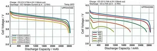
Capacity as a factor of temperature and load: 400 mA = 0.4C.

The left hand graph below from a Sanyo LiPo datasheet which was originally quoted. At 0.5C discharge the voltage drops below 3.5V at about 2400 mAh or 2400/2700 = 88% of nominal capacity of 2700 Ah.

The right hand graph shows discharge at a current of C/1 (~= 2700 mA) at various temperatures. At a temperature of 0 C (0 degrees Celsius) the voltage drops below 3.5V at about 1400 mAh, but at 25 C it's about 2400 mAh (as per left hand graph) so as temperature drops we can expect a substantial drop in capacity, but down to say 10 C you'd expect 2000 mAh or more. That's at C/1 discharge, the 400 mA = 0.4C in this example, and the 95% discharge rate of 5 mA will probably give close to full nominal capacity.

enter image description here

maxschlepzig
  • 426
  • 5
  • 17
Russell McMahon
  • 147,325
  • 18
  • 210
  • 386
  • This would simplify the layout; appreciate the above analysis -- But I have never used a part that provides up to ~500 mA with a low enough dropout (say 150 mV or less, similar to what you suggested); Is there a common such part? – boardbite Aug 26 '12 at 06:39
  • 1
    Using Digikey & Mouser, I have now found a few suitable and inexpensive LDO regulators that have low dropout voltage for 400-500 mA current. I have edited your Answer to include these options for future readers with an interest in Li-ion -> 3.3V – boardbite Aug 26 '12 at 07:24
  • @boardbite The TPS72633 link is broken - and I can't find any datasheets for it via google. For the TPS737xx I can't find its I_Q in the datasheet - that datasheet just specifies I_Q_shutdown. However, digikey lists that part with I_Q=400µA, which is quite high. For the LD39080, its I_Q is 1 mA, also relatively high. It seems like the Richtek RT9080, Ablic S-1155 and S-1172 parts have much better specs. – maxschlepzig Mar 13 '22 at 17:03
2

Get an LFP (Lithium ferrophosphate) battery. Nominal Voltage is about 3.2V and the working voltage ranges 3.0 to 3.3V. Draining your lithium Ion battery from 4.7V down below 3.7V is just detrimental to its life as it is inversely proportional to the depth of discharge

Abel Rwego
  • 29
  • 1
2

To be honest, a LDO regulator is probably good enough. When a Li-Po cell gets down to 3.3V, it has delivered most of its power (see lipo discharge curve). Many devices (esp8266, nrf24l01, etc.) that state nominal 3.3V supply will operate well below 3.3V.

As a practical example, I built a speedometer with wireless transmitter and receiver/display modules using NRF24L01 modules for the wireless and BA33BC0T linear regulators. Both transmitter and receiver cell voltage are shown on the receiver's display and in practice they cut out around 3.1-3.0V. I ride in (these devices operate in) temperatures from 5 to 30 degrees C.

Keeping in mind that this LDO regulator's datasheet quoted a 0.3V-0.5V I/O difference (I think?) and the NRF24L01 quotes a supply range 3.0V-3.6V, this is really good for a Li-Po project.

2

I would try one of the following methods:

  • boost the voltage until it doesn't drop below 3.3V and then regulate down to this value
  • use two batteries in series
  • try to redesign the circut; some ICs with nominal voltage of 3.3V will work even at 2.5V
Kamil Domański
  • 500
  • 4
  • 7
  • The 2nd and 3rd ideas, while good to know, aren't options in my case. Regarding the 1st option, wouldn't you say that separately boosting it first and then regulating it, is a fairly inefficient method? – boardbite Aug 25 '12 at 09:20
  • Indeed, however nothing else comes to my mind. – Kamil Domański Aug 25 '12 at 09:24