21

To power my microcontroller (ATmega8), I am using a ~5.4V voltage source. I want to ensure that I don't accidentally connect the voltage source in reverse, and figured a diode would be a nice way to accomplish this as from what I have learned so far, a diode allows current to flow in one direction, and blocks it in the other.

But what I also learned is that diodes create drops in voltage. I have a few of the typical diodes (1N4001, 1N4148, etc.), and would like to use them to achieve the aforementioned result without dropping the voltage as it would be too low to power the IC.

My question is, is there any way to do this with a diode? Or do I need some other component (if so, what would you recommend)?

Anindo Ghosh
  • 50,188
  • 8
  • 103
  • 200
capcom
  • 5,882
  • 14
  • 48
  • 59
  • What voltage would be "too low" to power the IC? Is 5.4V the minimum operating voltage? If you can go down to 5V, a germanium diode has only a ~0.3V drop. – Kit Scuzz Aug 25 '12 at 01:38
  • 6
    There is a way to use _ONLY_ a single MOSFET instead of a diode. The MOSFET will give you almost zero voltage drop. I'm sure if you Google it you'll see it. The reason why this is a comment instead of an answer is that I don't have time right now to google it myself and draw some schematics. I'll +1 any answer that does this. –  Aug 25 '12 at 01:45
  • Probably this is not an answer for your question but I remember we used to have vacuum tube diodes and they had no such problem. Just wanted to make some nostalgia. I know that they have different problems. – Celal Ergün Aug 25 '12 at 07:59

7 Answers7

33

An actual diode is limited by the laws of Physics [tm]. Actual voltage will depend on current and voltage and device used but, as a guide, under very light loading a Schottky diode may manage somewhat under 0.3V but this typically rises to 0.6V + as loading approaches maximum allowed. High current devices may have forward voltage drops of well over 1V. Silicon diodes are worse by a factor of two to three.

Using a MOSFET in place of a diode provides a resistive channel so that voltage drop is proportional to current and can be much lower than for a diode.

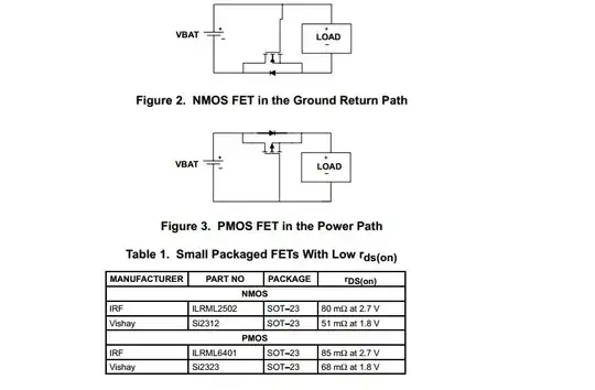
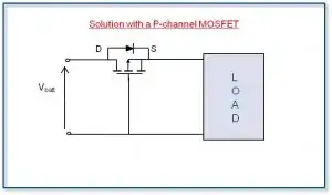
Using a P Channel MOSFET as shown below causes the MOSFET to be turned on when the battery polarity is correct and turned off when the battery is reversed. Circuit and others from here I have used this arrangement commercially (using the mirror image arrangement with an N Channel MOSFET in the ground lead) for a number of years with good success.

When the battery polarity is NOT correct the MOSFET gate is positive relative to the source and the MOSFET gate source 'junction' is reverse biased, so the MOSFET is turned off.

When the battery polarity is correct the MOSFET gate is negative relative to the source and the MOSFET is correctly biased on and load current "sees" on the FET Rdson = on tresistance. How much this is depends on the FET chosen but 10 milliohms FETs are relatibely common. At 10 mOhm and 1A you get only 10 milli-Volt drop. Even a MOSFET with Rdson of 100 milliohm will only drop 0.1 Volt per amp carried - far less than even a Schottky diode.

enter image description here


TI application note Reverse current / battery protection circuits

Same concept as above. N & P channel versions. MOSFETs cited are examples only. Note that the gate voltage Vgsth needs to be well below the minimum battery voltage.

enter image description here

Russell McMahon
  • 147,325
  • 18
  • 210
  • 386
  • 1
    +1. this devices are marketed as "Ideal Diodes" based power path controllers –  Aug 25 '12 at 02:44
  • Hmm, that is interesting. Thanks! Do you recommend any common MOSFETs to have in my parts bin? I am just starting to build my collection of components, and could really use some recommendations. – capcom Aug 25 '12 at 13:05
17

You do not want an as low as possible voltage drop. The ATmega8 is specified for 2.7 V to 5.5 V operation, and that 5.5 V is actually 5.0 V with some margin. In the datasheet you'll see many parameters specified at 5 V.

Your supply voltage is ~5.4 V. What does the "~" mean? That it may vary by a few percent? 3 % higher gives you 5.56 V, which is out of spec. It won't cause the AVR to go up in flames, but it's a good habit to stick to the specs.

So let the voltage drop. Allow a 500 mV drop. The ATmega will consume only a couple tens of mA. A 1N4148 will drop typically 900 mV at 50 mA, which I would accept gladly, but which you may find too high. In that case go for the Schottky, like also suggested in other answers. You don't want a Schottky diode with a 100 mV drop, go purposely for one with worse specs. This one will drop 450 mV at 100 mA.

stevenvh
  • 145,145
  • 21
  • 455
  • 667
  • That's great advice, thanks. By the "~" I meant about 5.4x V. The thing is, I would be using different voltage sources too. Sometimes I would use the 5.4 V one, but sometimes a 5.0 V one (from a USB port for instance). It don't want to dip below 5.0 V, that's for certain, which is why I was interested in finding a component which would cause a very small drop in case I use a flat 5V source. Thanks, let me know if you have any further suggestions, I'll grab some of the Schottkys you mentioned. – capcom Aug 25 '12 at 13:10
  • What if I used something like the 1N5817 http://www.fairchildsemi.com/ds/1N/1N5818.pdf ? Would that work to satisfy my purposes? – capcom Aug 25 '12 at 13:19
  • 1
    @capcom - The 1N5817/8/9 was actually the first diode I looked at, but I chose the other one because the voltage drop is a bit higher. Fig.2 in the datasheet says 350 mV for the 1N5818 at 100 mA, 400 mV for the 1N5819, so yes they are suitable too. But why don't you want to go below 5 V? The AVR can handle it easily. – stevenvh Aug 25 '12 at 14:06
  • Thanks, that's true; I don't *have* to run my AVR at 5V. But if I run it below 5 V, will the output pins still deliver 5 V outputs? I wouldn't suppose so, and I need 5 V outputs. Also, I tried hooking up a 1N4148 diode to my 5 V power source, and I want to ensure my observations are correct. The diode reverses voltage when the voltage source is connected backwards (so, gives -5 V), but does not allow current to pass. Initially, I was under the impression that a diode shuts off the circuit like a switch if the voltage source is connected in reverse. Thanks again, Steven. – capcom Aug 25 '12 at 16:11
  • 1
    @capcom - If Vcc is 4.8 V then that's what the output will deliver also. But if other devices are also powered from that 4.8 V they don't require 5 V, they'll need 4.8 V as well. Because it's an imperfect world and a lot can happen to a digital level IC designers provide a wide margin: most often anything above 0.7 x Vcc will be seen as a high level. So even if you connect the 4.8 V output to a 5 V device it will see a high level, even 3.5 V would do. – stevenvh Aug 25 '12 at 16:19
  • 1
    @capcom - It *does* shut it off like a switch. If you would use a switch instead of the diode, and open it you would also have the full voltage of 5 V across it. – stevenvh Aug 25 '12 at 16:21
  • Thanks Steven, that makes sense. But when the diode is *closed*, unlike a switch, it seems to pass a negative voltage. A switch would pass 0 V. Is that right? – capcom Aug 25 '12 at 17:17
  • @capcom - Yes, the conducting diode (we don't say "closed") will drop anything from some 100 mV to several volts, depending on the type (several volts for instance for a LED, but don't use that as a blocking diode, because it can't stand the reverse voltage). The switch will *also* drop an ignorable voltage, in the order of a mV, because the contact is not a perfect 0 ohm. [This one](http://media.digikey.com/pdf/Data%20Sheets/Tyco%20Electronics%20Alcoswitch%20PDFs/PRA,PRB,PRD%20Series.pdf) may have a 50 mOhm contact resistance = 5 mV drop at 100 mA. – stevenvh Aug 25 '12 at 17:28
  • Thanks, makes perfect sense. Also, I just tried using the diode with my voltage source and the AVR. The AVR seems to be getting about 4.2 V. For me, the surprising part is that it is working, seemingly perfectly. But the data sheet says that it needs 4.5 V - 5.5 V. How is this possible? Thanks. – capcom Aug 25 '12 at 18:23
  • @capcom - 4.2 V from 5.4?? That's large drop, what diode is that? You won't have that with the Schottky. The 4.5 V - 5.5 V is the range it was designed for, and at which it will definitely work. Which doesn't mean it definitely *won't* work if you go beyond that. It just isn't guaranteed anymore, and you shouldn't do this in any design. I once wanted to know how low I could go for an MSP430, which was specified at 1.8 V minimum. Well, that still ran at 1.3 V, but in my design I neatly used 3.3 V. :-) – stevenvh Aug 25 '12 at 18:35
  • Oh no, sorry, I was unclear. I was using the USB port's voltage source, so it was at 5.1 V, and I just checked again and found it dropped it to 4.33 V. I am using the 1N4148. That is still below 4.5 V, and as you said, I shouldn't go below or above what it is designed for. I guess when I get my Schottky diodes, it will bring it down to a more favorable voltage. But even at 4.33 V, it seems to be working alright so far. – capcom Aug 25 '12 at 19:08
11

Two ideas:

  1. Use a Schottky diode instead of the normal PN junction diode. Schottky diodes have less voltage drop than PN diodes.
  2. Connect the diode across the supply so that it is normally reverse biased. When the power is connected backwards the diode will conduct and prevent the reverse voltage from exceeding the diode's forward voltage drop. You will need a current-limited supply or a fuse upstream of the diode so that it isn't asked to carry unlimited current.
markrages
  • 19,905
  • 7
  • 59
  • 96
  • I call 2. the 'fools diode' and include it in all my circuits. It has saved me quite a few times :) It can be combined with a fuse or polyfuse (self-resetting). – Wouter van Ooijen Aug 25 '12 at 07:17
5
  • A Schottky power diode will give you a voltage drop as low as 0.2V
  • There are many connectors available which cannot be plugged in reverse.
  • Many people use a three pin connector with two wires attached. In this case plugging in reverse does not connect both wires.
Kamil Domański
  • 500
  • 4
  • 7
  • Up voted for the purity and simplicity of your third bullet point. As soon as I read that I knew my solution and proceeded to kick myself for not thinking of something so perfect and simple and for spending 3 hours researching P-Channel MOSFETs. Thank you. – SRM Oct 04 '12 at 17:38
  • 1
    If using a 3-pin connector with symmetry that permits reversal, instead of an open circuit, make the pinout symmetric as well. For example, positive on the center pin, return on both outer pins. – Ben Voigt Jan 24 '17 at 07:07
1

You guys miss how to get a zero voltage drop diode. Take 2 diodes, say 1Nwhocares. Bias one on via a resistor, get the .6V or so out and apply it to the anode of the other diode via a second resistor. Run the second diode's cathode to ground with a third resistor. The second diode is now biased on by the first diode. Put a cap input to the second diode's anode to get DC isolation. Shazam, an input AC signals gets rectified without any appreciable diode voltage drop. Forget the germaniums and Shottkys, at best you get like .3 v. Easy to adjust my circuit to get a .05 voltage drop. Just make the first diode's current higher to obtain a higher voltage drop. Makes a zero crossing comparator really pretty. Say good by to phase errors. Tweaks? Put a cap across the first diode, get rid of noise. Make the resistor going to the second diode's anode rather large. Helps with small signals.

  • 1
    you might have misread the question, the OP asked about protecting against polarity reversal. – Oleg Mazurov Feb 04 '15 at 04:39
  • I'd like some clarification on this, but because it's off topic here, please see my question about it: http://electronics.stackexchange.com/q/164782/53375 Thanks! – AaronD Apr 14 '15 at 16:15
  • @John M. Kelly, Clever trick… We can name it "diode compensation" or, more generally, "passive compensation" (removing something positive by equivalent negative). As you described, I have seen it for the first type in H&H. Of course, someone can say that this is simply the biasing idea. Anyway... I am sorry you left SE... – Circuit fantasist Aug 07 '20 at 10:47
0

A Schottky diode would be a good solution and it's what I ended up choosing for power path polarity protection on a PIC development board I made this week. Schottky diodes have a very low voltage drop compared to many other diode types, notably the general purpose ones. A popular use for Schottky diodes is to use them for high frequency circuits since they have a fast switching speed, though they are also known for their low forward voltage drop. A drawback to them, however, is their relatively lower breakdown voltage compared to other diode types. If you're just looking for polarity protection for a 3.3v/5v microcontroller or other low-voltage application, this might be ideal for you because the low voltage drop is appealing and the low breakdown voltage is still probably higher than you need. Pick a diode with specs that match your required maximum voltage drop at expected current draw, load current draw, and breakdown voltage. Digikey.com makes this very easy; it should be very straightforward from there.

0

To protect a circuit from reverse polarity using a diode but with no diode drop, replace the diode with a fuse, and connect a fairly large diode in reverse polarity across the power rails, after the fuse of course. It must be able to continuously handle the maximum current of the fuse as well a high pulse rating, which diodes generally can do.

This is how all the power inverters work. They can draw hundreds of Amps at 12 Volts, but reverse polarity only blows the fuses.

Another solution for low current devices is to replace the fuse with a resistor. The Voltage drop across the resistor can be less than a diode at low currents.

Another way is to use a diode in a MOSFET, since a MOSFET has a diode inside it. To protect the positive supply, use a P-channel device in such a way that the diode protects the device from reverse polarity with the gate turned off. Now you just have to make some logic (such as a single resistor and small signal diode) to turn on the gate when the polarity is correct, then that .6 Volt diode drop will now turn in to the MOSFET's Rds MAX resistance or less. MOSFETs turn on in both directions.

Alex Cannon
  • 264
  • 2
  • 6