-1

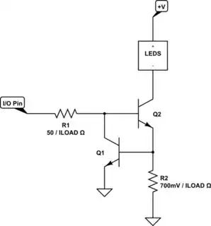
I want to build a simple circuit, to control a chain of LEDs via an external PWM signal but limit their current. Unfortunatly I'm not aware of all the effects that the transistor would introduce to this circuit. If someone could point out any simple enhancements to compensate for effects I haven't taken in account for I would be very gratful.

There is a current I1 flowing trough the LEDs and the collector, which I want to be constant. V2 is a uC GPIO output pin with an Von of 3.3V (which I assume is close to constant) and Voff of 0V. The current from V2, to which I refer as I2, will be split into I3 (transistor Base) and I4 (R2). I therefor know, Vsense = Rsense * (I1+I2).

Now there is Vbe, which I don't know if I should assume it as constant. First it is dependant of Ice, second it may vary between production lots, I don't know, how signifficant this effect is.

Two resistors also seem too simple, but if it works.. Or should I better put in a diode instead of R2 and adjust Usense + Ube = Vdiode.

My goal is to get a few improvments or related circuits that get around issues like frequency dependency, change of parameters over temperature, production lot related variance etc.

Please, for the sake of simplicity, assume all the parts in this schematic a capable of handling the resulting theremal dissapation.

schematic

simulate this circuit – Schematic created using CircuitLab

engelant
  • 59
  • 7
  • Is the current you want 40mA? Or? – jonk Jul 17 '18 at 18:08
  • It's more about the variation with this circuit as for current Values in mA. If it's valid for 1ma it should be valid for 10A. But if It helps, suume 20mA and 65mA. – engelant Jul 17 '18 at 18:16
  • No, the same circuit will not be valid for everything from \$1\:\text{mA}\$ to \$10\:\text{A}\$. Dissipation drives the higher current designs. – jonk Jul 17 '18 at 18:18
  • And in your case, you have \$24\:\text{V}\$ involved. If your LED loads do not take up most of that voltage overhead, then the transistor itself ***must*** do so. Imagine \$20\:\text{V}\$ across one BJT with \$10\:\text{A}\$ through it. That's \$200\:\text{W}\$ in the BJT!!! So: ***IT MATTERS***. – jonk Jul 17 '18 at 18:20

2 Answers2

3

You show a voltage rail of \$24\:\text{V}\$. This may be a matter of convenience for you, but isn't required by your load. Or it may be that your load requires most of it. You don't show the load current. So it's not really possible to proceed very far with a design. One is instead, it might seem, faced with writing a book on the topic.

I do see a comment you made saying that there is a "chain of LEDs." So I'll assume for the moment that most of the \$24\:\text{V}\$ will appear across that chain, leaving the BJT with a small remainder to deal with.

Something like this would be preferable to your circuit (which I don't want to discuss.)

schematic

simulate this circuit – Schematic created using CircuitLab

I show some rough formula guesses on the above schematic but the formulas are here: \$R_1=\beta_2\cdot\frac{3.3\:\text{V}-2\:\cdot\: 700\:\text{mV}}{\eta\cdot I_\text{LOAD}}\$ and \$R_2=\frac{700\:\text{mV}}{I_\text{LOAD}}\$. The value of \$\beta_2\$ should be conservative for an active-mode BJT (perhaps 100.) The value of \$\eta\$ is a "fudge factor" I just created. Here, it should be at least 2 and perhaps as large as 4. I'd probably use 3, myself. (It should never be used, smaller than 1.)

You can find a longish discussion of such a circuit here: CC using BJTs. The discussion there is much more detailed and also includes a BJT+MOSFET version of the above circuit, as well. It's probably worth reading through.

Be aware of your dissipation in \$Q_2\$. Small signal versions of BJTs are usually found in TO-92 or SOT-23 and have a very limited ability to dissipate. Larger TO-220 packages can handle more and you can add heat sinks to them, too. It is even possible to extend the above circuit to share the load current between several BJTs.

(It may be a good idea to keep \$Q_2\$ thermally isolated from \$Q_1\$, since \$Q_1\$ is measuring the current going to the LEDs.)

jonk
  • 77,059
  • 6
  • 73
  • 185
  • Yes, a small TO-92 transistor for Q2 (in ambient air) would almost certainly die from overheating. But adding more LEDs (in series) helps. Perhaps six (depending on their forward voltage) would allow a small Q2 to survive without a heat sink. This circuit is a major improvement, but still might not regulate well enough to compete with resolution of a 10-bit PWM. – glen_geek Jul 17 '18 at 19:20
  • @glen_geek Agreed that it will definitely *not* provide 10-bit PWM resolution. Not without calibration, thermal monitoring (or control), etc. Current mirror structures on ICs can help. But I was mostly trying to deal with a relatively bad design and to recommend some kind of improvement that might be understood by the OP (since I'd also written some stuff elsewhere on that.) – jonk Jul 17 '18 at 19:25
  • I must say my question was not related at all towards heat dissapation, that's easy to calculate. I will have a look at the link you provided me and read trough that discussion. At first glance I just see again, that Vbe is again constantly assumed with 700mV. – engelant Jul 17 '18 at 19:34
  • @engelant You can improve on the \$700\:\text{mV}\$ estimation by adjusting it by adding or subtracting \$60\:\text{mV}\$ for every factor of 10 change in the current. Small-signal BJTs will have about \$700\:\text{mV}\$ at \$2-5\:\text{mA}\$, thereabouts. So you can work up or down from there. For example, you might want \$60\:\text{mA}\$. This is about 10X to 30X. For a small signal device, I'd then estimate about \$60-90\:\text{mV}\$ more than \$700\:\text{mV}\$, or perhaps \$780\:\text{mV}\$ as a good guess. Q1 isn't dealing with that kind of current, luckily! So it will be less, not more. – jonk Jul 17 '18 at 19:40
  • So It's safe to assue the main Impact on Vbe drop is Ice. How large in terms of mV or % are other factors like chip temperature, operation frequency or difference between lots? – engelant Jul 17 '18 at 19:46
  • @engelant Lot differences may account for about \$\pm 30\:\text{mV}\$ (equivalent to about \$\pm 15\:^\circ\text{C}\$ due to temperature change.) A % calculation uses a "sensitivity equation," of the form: $$\frac{\frac{\text{d} y}{y}}{\frac{\text{d} x}{x}}=\frac{\text{d} y}{\text{d} x}\:\cdot\:\frac{x}{y}$$ But the above figures I gave cover most concerns. Frequency is another factor I can't address well here. You've provided far too little. But neither Q1 nor Q2 operate in saturation, so they aren't slowed down by having to "come out of" saturation, at least. – jonk Jul 17 '18 at 20:05
  • @engelant You may want to read [here](https://electronics.stackexchange.com/questions/375165/solving-unkonw-r1-and-r2-in-classic-descrete-bjt-bais-arangment/375269#375269) and [here](https://electronics.stackexchange.com/questions/373603/common-emitter-circuit-cant-understand-negative-feedback/373625#373625) to see sensitivity calculations in action. – jonk Jul 17 '18 at 20:10
  • Yepp, that's exactly the little trick I was locking for, keeping Vbe const by moving it to a low current branch. – engelant Jul 17 '18 at 21:01
1

This kind of current limiting is usually done with two diodes in series, forward biased, in place of R2. Then you know that \$V_B\approx\$1.4V and the voltage across \$R_{SENSE}\$ will be about 0.7V. Use Ohm's law to pick a value for the sense resistor that gives the desired current. The advantage of using diodes instead of a resistor divider is that you don't depend on a constant volage from the I/O pin.

Of course, there are many factors that will cause the current limit value to vary, as you mentioned. I would guess that you could achieve \$\pm\$10% regulation with a circuit like this. The current will never be constant, you must live with some variation but you didn't tell us what you need.

Elliot Alderson
  • 31,192
  • 5
  • 29
  • 67
  • What I need is a chain of LEDs, that operate with a given current for ilumination purposes. I want to be able to switch those via PWM with a resolution of up to 2^12bit with 300Hz. What I'm searching for is a well known circuit, which I'm unaware of, which improves the variance of mine. – engelant Jul 17 '18 at 18:25
  • 1
    So why won't you specify a tolerance on the current? How would we know whether a circuit is good enough for you if you don't give the requirements? – Elliot Alderson Jul 17 '18 at 18:47
  • I didn't specify the requirements of the desired current as I wanted to know at what cost which kind of tolerance comes. – engelant Jul 17 '18 at 19:37
  • That's being inconsiderate of the people who volunteer here to answer questions. You must have some idea of what you need...allowing people to spend their time providing answers that you immediately reject as not meeting your tolerance requirements is rude. – Elliot Alderson Jul 17 '18 at 19:57