0

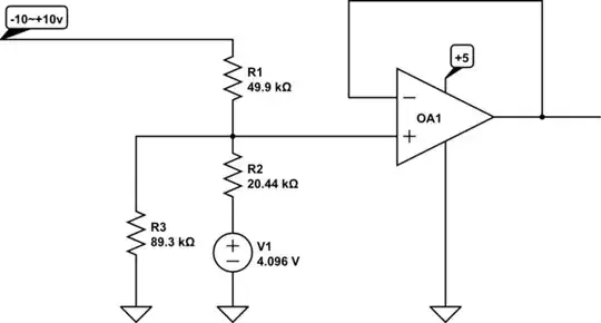
How can I design a buffer circuit that takes an input of +/- 10V and scales it down to a 0V to 5V.

The idea is to design a circuit that is microcontroller compatible (can be read by an analog-in pin by a typical 5V microcontroller) with input signals from Eurorack modular synthesizers outputting +/- 10V.

schematic

simulate this circuit – Schematic created using CircuitLab

I think I need a high impedance input but don't know what kind of transistors to use or what configuration to use them in.

Britt Kelly
  • 257
  • 1
  • 10
  • You have to define load current , efficiency and voltage tolerance and maybe dynamic loads – Tony Stewart EE75 Jul 15 '18 at 20:55
  • 1
    You need to know the required bandwidth. And it would be helpful to know the source impedance so you can get an idea of how high impedance your circuit actually needs to be. And also how much noise you can tolerate introducing. – Chris Stratton Jul 15 '18 at 20:57
  • https://electronics.stackexchange.com/questions/37095/level-shifting-a-2-5v-signal-to-0-5v Sorry I found the answer here for a simple starting point. Thanks for answers. – Britt Kelly Jul 15 '18 at 21:29

1 Answers1

1

Something like this will probably work for you:

For R1 = 49.900K the ideal value of R2 would be 20.43904K and R3 would be 89.331K approximately.

The 4.096V source could be a 0.1% tolerance series reference that can sink or source current such as ADR3440. You can play with the resistor values to make them from standard values for R2/R3 as you like so long as the ratio of R1:R2:R3 is kept the same and the values are not too high or too low.

There should be a bypass capacitor on the op-amp supply and input or output protection may be required in a real circuit.

The op-amp has to be a rail-to-rail input and output type for +5V only supply.

schematic

simulate this circuit – Schematic created using CircuitLab

Note that if you leave the input open you will get an output voltage of 3.333V.

Spehro Pefhany
  • 376,485
  • 21
  • 320
  • 842