-1

I have a device that is activated by grounding a pin that is pulled up to 24V.

I want to control this using a microcontroller (ESP8266 which operates at 5V) using as little components as possible (no relays, transistors).

It is easy to ground the pin by just writing LOW to the output of the microcontroller. And 'disconnect' the pin by setting it to INPUT.

Since the pin is only pulled up (not directly connected to 24V), is it safe to connect it directly to the microcontroller? If not, how can I do it (preferably using only resisters/diodes/etc)?

sunny-lan
  • 175
  • 1
  • 7
  • what is the pull-up resistor value? in simpleterms, you are violating the ESP8266 requirement of not exceeding certain voltage across the pins – User323693 Jul 14 '18 at 15:06
  • 1
    Absolutely not. You will need external active parts, period. – Spehro Pefhany Jul 14 '18 at 15:06
  • @Umar the pullup will probably be around 10K – sunny-lan Jul 14 '18 at 15:07
  • Also, when the "device" is activated, the current of about 2.3 mA will be flowing into the ESP device output pin. i do not know how much is the allowed current. never the less, applying high voltage at the input is not a good idea for long time. – User323693 Jul 14 '18 at 15:15
  • @sunny-lan - You said: "*no relays, transistors [...] preferably using only resisters/diodes/etc*" Please explain *exactly* why you have a limitation of *not* using relays or transistors, but *are* able to use other components. – SamGibson Jul 14 '18 at 15:16
  • @SamGibson I wanted to avoid using a PCB at all – sunny-lan Jul 14 '18 at 15:18
  • Possible duplicate of [Voltage level shifter](https://electronics.stackexchange.com/questions/546/voltage-level-shifter) – Dmitry Grigoryev Jul 14 '18 at 15:20
  • @sunny-lan "*I wanted to avoid using a PCB at all*" Thanks, but that doesn't answer my question :-( If you want to avoid using a PCB, how does this prevent relays or transistors being used? I have used both of those types of device without a PCB in the past. So, again, please explain *exactly* why you have a limitation of not using relays or transistors. – SamGibson Jul 14 '18 at 15:22
  • on a light note: https://i0.wp.com/cdn.makezine.com/uploads/2012/10/newimage.png – User323693 Jul 14 '18 at 15:23
  • @SamGibson Then I guess I will have to say its out of curiosity whether or not it is possible to be done without active components. – sunny-lan Jul 14 '18 at 15:27

3 Answers3

1

Do you have space for 3 components? they are tiny.

Please choose the values and part numbers as per your application need. just for representation.

Drive LOW from MCU to disable the external control circuit (active low)

Drive HIGH from MCU to enable the external control circuit

schematic


Opto couplers?

User323693
  • 9,151
  • 4
  • 21
  • 50
  • yes, that is what I was thinking on doing, I was just wondering if its possible to avoid any components at all – sunny-lan Jul 14 '18 at 15:17
1

@sunny-lan, even if you write the pin to be INPUT, there's still a protection diode from the IO pin to VDD inside the microcontroller. So if your VDD is 3 volts, you're basically still pulling the pin low to 3.6 volts even if you set the pin as INPUT. If you set it as OUTPUT, LOW then you're pulling it low to zero volts.

I know everybody is saying that you shouldn't connect the IO pin to a 24V pulled up pin, and they're basically right. But the only way to be sure is to find the absolute maximum ratings in the datasheet and I cannot find them. 10 k pull-up to 24 volts is 2.4 milliamps and the protection diode just might be able to sink that amount of current. But whether you could control the external device or not, that's another matter. Remember, you're only going to be able to make a 3.6V difference in the voltage at the MCUs end. Depending entirely on what is the Vil/Vih decision level point in the external equipment, you might be able to find a series resistor value that allows you to swing over that decision threshold.

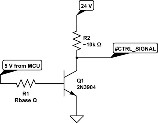
But you're basically probably going to destroy your ESP8266 in the process. Especially if your ESP is unpowered and there's nothing to sink that current, and the 2.4mA from the pin lifts the power rail over something like 5 volts, the chip is dead. And the NPN suggested by Umar only costs something like 2 cents US or less than 0.1 RMB so why not use it. It's the only practical way to do it, really...

PkP
  • 7,567
  • 2
  • 23
  • 42
  • 1
    There's another problem with out-of-range voltages - if the protection diode survives, where does the current go? Into the board's power supply basically, which means it can end up lifting up the power rail. This can get particularly problematic if the board itself isn't yet powered - you may find for example that it won't do a reset when logic power is applied, because it was already "partially" on. In effect the voltage will hover just below the point where components would start drawing notable power, but this can be enough to retain bad state and prevent the power on reset from working. – Chris Stratton Jul 14 '18 at 16:14
  • @ChrisStratton, that's a valid consideration. There must be a load that can sink those milliamperes. And a very good point about the reset. That's very true. – PkP Jul 14 '18 at 16:20
0

You should NEVER use the digital I/O pin bulk diode as part of your design.

You may potentially raise the power supply voltage for your MCU if it was ever in a sleep state (low uA current draw). The current it would attempt to draw from the 24V supply may be enough to turn off (at best) the LDO supplying your MCU, and at the worst raise the at sleep VCC to a dangerous level.

You could achieve an interface to 24V as you want with a single FET:

schematic

simulate this circuit – Schematic created using CircuitLab

The FET noted above is a TO-92 so easy to handle (available from Digikey) and there are many more if you can handle surface mount packages.

Jack Creasey
  • 21,428
  • 2
  • 15
  • 29