I have a slight confusion in how the feedback pin works. The "\$V_{ref} \times (1 + R_1 / R_2)\$" seems like a shortcut to me, and I have trouble understanding how to feed a voltage in to it, to say make a tracking pre-regulator to always maintain +2 volts.
The circuit I am designing starts fairly simple, it looks roughly like this:
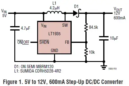
From what I understand, you have 5V running past D1 and feeding 5V in to the resistive divider (at very start), making $$\frac{10k}{84.5k+10k}\times5V=0.52V$$
That is fed in to the error amplifier, of which the reference voltage from datasheet I assume is 1.265V
And so it tries to bring 0.52->1.265V, making $$5V\times\frac{1.265}{0.52}=12V$$
The above is new to me and I had discovered the correlation while writing it. Is that how the error amplifier works?
If I want say...7V, I would cause the voltage to the FB pin to be (7/5) times lower than 1.265V so it will work itself up to 7V as my formula above? (excuse that math if minor mistake, but more or less using the difference in FB and Vref to multiply the input voltage).