1

I need help identifying which wire is which inside my USB cable. So I stripped the outer insulator for the USB cable, and it revealed 4 wires: Red, White, Green, and Yellow.

I thought Red would be VCC, but then I checked the circuit board for the mouse I ripped it off of and the board labeled where the four wires were soldered on.

It showed four characters each associated with a wire color: V (White), G (Green), D (Yellow), C (Red). Very strange from what I have learned about USB so far, but strangest being that Red is not VCC! Why is there no standard for these wire colors?

Anyways, how can I confirm which is which (VCC, GND, D-, D+)? I have a multimeter, and confirmed that between White and Green, White and Red, and White and Yellow, there is 5V. I don't think that is much of a development, but what should I do?

I do have other USB cables lying around as well, but that's an easy way out and my absolute last resort. Thanks.
capcom
  • 5,882
  • 14
  • 48
  • 59
  • 2
    Test connectivity between each exposed wire and the pins on the connectorized end of the cable? – The Photon Aug 22 '12 at 17:31
  • And then once you know which pin on the connector corresponds to which wire... http://www.reuk.co.uk/OtherImages/usb-connector.jpg – NickHalden Aug 22 '12 at 17:34
  • @ThePhoton Sorry, what do you mean? It sounds like a statement and question mixed accidentally, and I'm unfamiliar with the term *connectorized* - sorry, I'm new to electronics. – capcom Aug 22 '12 at 17:39
  • @JGord Apologies if I was unclear, but the part I am having difficulty with **is** finding out which pin on the connector corresponds to which wire. Do you mean I should dissect the male end of the cable to see where each wire goes and work backwards? – capcom Aug 22 '12 at 17:41
  • 1
    Photon means to test the wires against the pins on the connector, so that you can say "red = pin 1" etc. The pin assignments are unambiguous. – stevenvh Aug 22 '12 at 17:41
  • @stevenvh I see. What would be the best and safest way to do this? I can't test the pins on the connector while it is plugged in, because they are blocked. Thanks. – capcom Aug 22 '12 at 17:49
  • Pin assignments for A and B type connectors are here on Wikipedia: http://en.wikipedia.org/wiki/File:USB.svg If you are looking at mini or micro connectors it shouldn't be too hard to find those assignments either. – The Photon Aug 22 '12 at 17:50
  • Do you have a multimeter? Measure the resistance between wire and pin. – stevenvh Aug 22 '12 at 17:50
  • Disconnect the cable at both ends. Use an ohm-meter or continuity tester. Touch one probe of the meter to one pin of the connector. Touch the other probe to one of the wires. If the wire is connected to the pin, you'll see (near) zero ohms, or get a beep for continuity. – The Photon Aug 22 '12 at 17:51
  • You can get a multimeter capable of doing this test for $10 - $20 at any hardware store ... If you get a really cheap one, don't trust it to really be safe for use on mains voltages. – The Photon Aug 22 '12 at 17:53
  • @stevenvh Thanks, your method worked perfectly. I never knew there was a detectable amount of resistance in a 2.5 foot long wire. Learned a lot of new things from this little exercise alone. If you want to leave an answer briefly outlining what you commented, I'd be glad to select it as a best answer. – capcom Aug 22 '12 at 18:02
  • @ThePhoton Thanks, your method (same as Steven's) worked perfectly! He wrote it first, but if he doesn't leave an answer, feel free to and I will choose it as the best one. – capcom Aug 22 '12 at 18:04
  • Thanks, but I'll leave this one for @ThePhoton. He mentioned measuring first and gave details. – stevenvh Aug 22 '12 at 18:05
  • Will be a few hours --- when I'm home from work. – The Photon Aug 22 '12 at 18:07
  • @capcom, You probably didn't measure the actual resistance on 2.5 feet of cable. To check, just touch the two probes of your ohmmeter together. You'll probably see a couple of tenths of an ohm just for the different contacts from the meter to the probe wires, etc. To measure something like a copper wire you need a more sophisticated ("4-wire") setup. – The Photon Aug 22 '12 at 18:10
  • @stevenvh Very kind of you. – capcom Aug 22 '12 at 18:18
  • @ThePhoton Hmm, I see. Well, it was interesting nonetheless! – capcom Aug 22 '12 at 18:19
  • Thanks for this Capcom - I just cut one with the same colors and it was driving me crazy! I just wanted to charge a Cell Battery via connecting wires but it's frustrating when there isn't a wiring standard to things like this :-) –  Jul 09 '14 at 22:07

1 Answers1

7

It's easy to just test the connectivity from the pins on the connector-end of the cable to the bare wires at the other end.

Even a hardware store multimeter is good enough for this test.

Disconnect the cable at both ends. Set your meter to the ohms function.

Touch one probe of the meter to one pin of the connector. Touch the other probe to one of the wires. If the wire is connected to the pin, you'll see (near) zero ohms. Depending on your meter you might also get a beep for continuity.

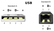
The pin assignments for the connector are readily available. Here's a picture from Wikipedia: enter image description here

If your connector is a mini or micro type, those pinouts are also available from the Wikipedia article on USB.

The Photon
  • 126,425
  • 3
  • 159
  • 304