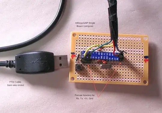
-6

I recently started working on a little self balancing robot using ATmega328P. I made a simple PCB with an ATmega, a L293D, terminals for 2 motors and a MPU 6050 and so on.

I have a huge 25V 2200uF capacitor across the main power supply on the pcb but I don't suppose it is causing problems because it worked flawlessly yesterday.

The L293D heats up really bad because the motors switch directions extremely rapidly. And it is right next to the ATmega. I don't think that causes any problems? Motors are powered by another source.

The MPU's Vcc and ground are not decoupled with capacitors but I haven't seen problems with resetting since I twisted the wires coming from motor.

I am programming with USBasp (probably a clone made in china). It supplies 5 point something on Vcc and ground.

I power the motor and the circuit using 2 mobile phone chargers which both output at most 5.2 volts.

This same setup was working flawlessly yesterday. Today, however, the MCU doesn't work (its probably fried). I tried switching it with a new MCU. That also fried. How can this be?

Apart from general suggestions/deductions, if you want any specifics I will post schematics/photo of the circuit. Please help me out here.
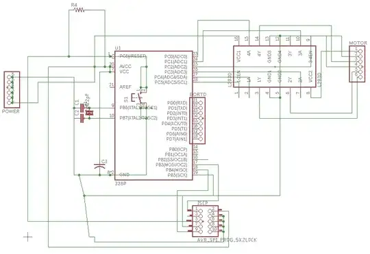
schematic

3 Answers3

6

No capacitors on the MCU supply pins. No diodes on the motors. The latter probably caused the MCU to be zapped.

Leon Heller
  • 38,774
  • 2
  • 60
  • 96
  • L293D has built-in flyback diodes. – Bhuwan Adhikari Jul 12 '18 at 06:44
  • Sure, but then explain why the datasheet still shows external diodes as well. For some applications (with small motors perhaps) the internal diodes might suffice but that might not be the case for larger motors. Since the datasheet shows diodes I would add them anyway for safety. – Bimpelrekkie Jul 12 '18 at 06:50
  • I also agree with the lack of capacitors issue, the flyback spikes from motors have high frequency component which a huge 25V 2200uF simply ignores, it cannot handle high frequencies. That might cause voltage spikes on the supply and that could damage all ICs. Add 100 nF ceramic caps near every supply pin like all sane circuit designers do. – Bimpelrekkie Jul 12 '18 at 06:54
  • @Bimpelrekkie The datasheet also clearly says: "On the L293, external high-speed output clamp diodes should be used for inductive transient suppression. On the L293D, these diodes are integrated to reduce system complexity and overall system size". The problem is somewhere else. – Maple Jul 12 '18 at 07:05
  • @Maple OK, didn't see that, still the issues about the decoupling capacitors still stands. The diodes feed the spikes to the supply lines so these will need decoupling. – Bimpelrekkie Jul 12 '18 at 07:11
  • @Bimpelrekkie They do not feed spikes to the **MCU supply** lines, since motors powered from separate supply. The decoupling is necessary, of course. The cheap switching cellphone charger might be feeding more noise there than motors could achieve – Maple Jul 12 '18 at 07:13
3

Why did your microcontroller die?

Sloppy engineering!

There is no point analyzing the circuit, because the underlying problem is already abundantly evident from the schematic.

The details matter in engineering, so the "Eh, who cares" attitude exhibited by your schematic will get you into trouble. When you don't take care of the little things, it's a good indication that you don't bother getting the big things right either.

Giving people a sloppy work product is not only providing clear evidence of sloppy work and sloppy thinking, but it is also insulting those you ask to look at it. Stop and actually think about it. A sloppy schematic says "My time to clean this up isn't worth you're aggrevation." The corollary is "I'm more important that you are."

Just look at this mess!

  1. There are parts on top of other parts.

    enter image description here

  2. You couldn't be bothered to rotate text to make it easily readable.

  3. There is text from different parts colliding so that it's hard to read any of it.

  4. Then what's with this ratsnest!? Note that most of these traces are actually connected together, and therefore represent the single power net. Given that, it could have been drawn much more simply and therefore invite less confusion.

  5. You couldn't even be bothered to clean up this mess. Really!?

  6. Some connections have proper junction dots, but others that seem to be connections don't. Not only is this very sloppy, but in this case it's also just plain wrong. Eagle (it's obvious that's the software you are using) automatically places junction dots at forks of the same net. The fact that Eagle doesn't show junction dots in some places means that the nets are not really connected according to the internal data structures. The circuit isn't what you think it is.

    In this case, it's really not clear what is connected to what, and almost certainly what Eagle thinks is connected is not what you intended.

In short, this is a sloppy mess that you should have been ashamed to show anyone. You need to seriously adjust your attitude and clean up your act if you ever want to be good at engineering or have others take you seriously.

This mess doesn't deserve any further answer here. Thumbing your nose at the volunteers you seek a favor from was a really stupid move. We don't want crap like this dumped on us. Go away until you grow up and take your work seriously.

Olin Lathrop
  • 310,974
  • 36
  • 428
  • 915
2

I recommend two things:

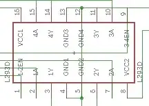
1) Clean up the mess on your schematics and then check your connections again. For example, 3A and 3-4EN pins on L293D look like they connected to GND, as well as SCK on the MCU. You could have left the sloppy schematics as is, thinking "I'll remember what goes where" and later when you assembled the circuit you could have followed it as it was drawn and made wrong connections.

Note that Eagle does not need wires to be "dotted" to make a connection. If you use auto-routing to make your PCB you can end up with wrong connections without realizing it.

2) Add 0.1 uF caps near supply pins. Almost all mobile chargers are switching mode nowadays. Cheap ones can put out a lot of noise and yours already supply 5.2V instead of 5. Even 0.4V spike will push MCU over the limit.

I would even go as far as use 4.5-5V LDO with much smaller caps before and after. It is a mistake to think that adding one huge capacitor can replace properly selected decoupling.

Also, "L293D heats up because the motors switch directions extremely rapidly" does not make much sense. They are designed to switch rapidly. Check the current draw of your motors. L293D is only rated for 600 mA. Do you have enough copper around ground pins? They are used as heat sinks and should be "Connected to printed-circuit-board ground plane with multiple solid vias" per datasheet.

Maple
  • 11,755
  • 2
  • 20
  • 56