1

Disclaimer: I am a novice.

I have an RS232 connection with an RFID tag reader which I am monitoring via software on a desktop computer as well as an Arduino. The device is configured with 8E1 parity. The arduino is (to the best of my knowledge) set up for 8N1 parity. Both the computer and arduino connect directly to the reader, and receive the exact same signal.

The arduino is reading a tag as follows:

10 00 62 00 10 29 C0 0F 00 39 12 C0 56 00 8D 0A

The computer is reading the same tag as follows:

30 00 E2 00 30 69 80 0F 00 59 12 80 96 00 0D 0A

With my (limited) understanding of parity, I can't figure out the conversion here. How is the arduino interpreting these bits to obtain those values?

3 Answers3

1

Thanks for all the help.

After doing some investigation with an oscilloscope, I've figured out what's going on:

Sample pure data from reader (LSB first, spaces added for clarity):

10 0000 11000 10 0000 00000 10 0100 01110 10 1011 00001 10 0101 00000 10
^s 0    ^3  ^p^s ^0   ^0  ^p^s ^2   ^E  ^p^s ^D   ^0  ^p^s ^A   ^0    ^s

For a data value of

0 3 0 0 2 E D 0 A 0  -> 30 00 E2 0D 0A

s is the stop indicator, p is the parity bit, and others are the hex data. What is happening on my arduino is that the parity bit is being read as the most significant bit for the second half of the byte, then the previous least significant bit is used to overwrite the new least significant bit of that half-byte.

Applied to the previous example:

11000 -> 1000
00000 -> 0000
01110 -> 0110
00001 -> 0001
00000 -> 0000

which produces:

0 1 0 0 2 6 D 8 A 0 -> 10 00 62 8D 0A

explaining the conversion that you see in my original example at the start and end bytes:

30 00 E2 0D 0A -> 10 00 62 8D 0A

If for some reason anyone else runs into this incredibly specific problem, I've converted the data back in the arduino logic with these functions (no they're not optimal):

byte fixBits(byte rc) {
    byte five = rc & 0x10;
    byte six = getParity(rc) << 5;
    byte hex1 = (rc & 0xF0) << 1;
    byte hex2 = rc & 0x0F;
    return ((hex2 | hex1) & 0xCF) | five | six; // bit masking
}

byte getParity(byte rc) {
    int sum = 0;
    byte test = rc;
    for (int i = 0; i < 8; i++) {
        sum += test & 1;
        test >> 1;
    }
    return sum & 1;
}

If anyone can describe exactly why this is happening I'd be curious to hear it, but otherwise this issue is solved.
1

Your tag reader is sending serial data with a parity bit, and the Arduino isn't configured to expect that.

You have two options:

  1. Configure the Arduino to read the parity bit by passing SERIAL_8E1 as the second argument to Serial.begin(). Once you've done this, the data should be received normally.

  2. Configure the device to not send a parity bit. (The manual implies that this is an option.)

The method that you've come up with is nonoptimal. It's likely to result in unpredictable, data-dependent read errors.

  • Everything in this answer is correct. Unfortunately, i'm using SoftwareSerial, which does not have the second argument, and setting the device to not use parity bits causes significant usability issues when configuring (i.e., it won't changes settings). Ultimately, once I'm more confident in the rest of my program I will probably switch to using Serial.begin() with the setting you've described. – Kevin de Haan Jul 17 '18 at 22:26
0

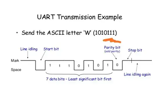
Parity bit will not be part of data. If you have an oscilloscope or a logic analyzer plugin and monitor the bits one by one. You will understand.

enter image description here Ardiino is not configured to expect parity bit. Presently, arduino will be reporting errors for cases where parity bit is not one. Monitor UART error status registers. Arduino is expecting the location where parity bit is put (by the RFID reader) to be one always.. (STOP bit)


How is the computer interpreting these bits to obtain those values?

Computer will not operate on the received data. It will extract data from databits position as is.. And then computes the parity.. If the received parity doesn't match with computed parity, a parity error flag will be set in the error register. It is then task of the program to check it status whenever the data is received from the RFID.

User323693
  • 9,151
  • 4
  • 21
  • 50