OK, I bought this little remote-controlled Ac outlet thing for $1. It controls 3 outlets via RF. I didn't realize it was RF at first, but I currently have my BeagleBone Black doing a bunch of home automation stuff on my network anyway, and figure I can wire in the remote into the BBB via a couple transistors and be on my way.
I can't read the chip in the remote, it's blank. Supply is a 3V coin cell battery, but I figure I can run it from the 3.3V supply of the BeagleBone (maybe with a resistor to drop the voltage? Or should it be okay at 3.3V? I'm thinking it should be okay at 3.3V). There are 6 buttons, 3 for on, 3 for off. There are two positive rails, one for all the on buttons, one for the offs. Each of these rails connects to a different pin. The buttons connect the positive rail to different pins.
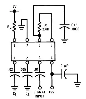
For schematic see @Transistor 's post below.
Some of this is a bit sketchy and I purposely omitted what looks like a power supply cap, all the antennae stuff (P1 and P7 I think). Hopefully, it gives you an idea of what I'm looking at.
So, if I drop a few GP PNP transistors over the ends of each switch, then connect base to different GPIO pins on the BeagleBone, then dropping the GPIO pin low should make the transistor conduct, right? The GPIO pins on the BBB are also 3.3V and current in minimal, so what sort of resistors am I looking at to avoid frying stuff?
I'm a software guy, not a hardware guy. Any and all help is greatly appreciated!!
Edit: Working now and Google Assistant can now control the AC outlets I bought (3 for $1). I have a purple livingroom light and a big fan connected right now. Not using number 3 (yet). Software will be made more robust later, but really cool to have it on my phone now