5

enter image description here

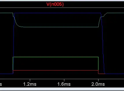
I am using this switching circuit to switch a lamp. I am controlling a rising slew rate at Vout (from 0-Vcc) that is adjustable by setting R2 with a poteniometer. It's not necessary for my project, but I would like to control the switch-off time for the MOSFET. Here is a my output at R6 with a 3.3v input.

enter image description here

As far as I understand it, Vout is staying high after Vin has gone low because the FET will stay on until Vgs is below the threshold voltage, so it makes sense that Vout stays high until Vgs goes below the threshold, but why is the slope after that point so much shallower than the rising Vout slow?

How could I reduce the fall-time of the voltage at Vout? This post has shed some light on the issue, but I haven't been able to figure out a good solution yet. I'm somewhat of a beginner to electronics, so any help is really appreciated.

EDIT:

Simulation with Vg

enter image description here

Peter Kapteyn
  • 115
  • 1
  • 6

3 Answers3

7

A very effective way of reducing the MOSFET turn-off time if you are driving it by a single pull-up (or pull-down, as it is in the case of a P-channel MOSFET) is to use an active pull-down (pull-up in our case circuit). This can be realized simply as follows:

schematic

simulate this circuit – Schematic created using CircuitLab

The circuit works according to the following points:

  • When the current mirror turns on, the \$I_{C1}\$ current flows through \$R_1\$, \$D_1\$ and the MOSFET gate-source capacity \$C_{GS}\$, charging it by increasing the gate charge \$Q_G\$ up to its turn-on value. \$Q_3\$ is off since it is a NPN BJT and its \$V_{BE}\$ is less than zero during this switching phase.
  • When the current mirror turns off, the current stops to flow through \$R_1\$ and and the voltage of the cathode of \$D_1\$ starts to rise, while its anode voltage is kept constant by the (large) gate charge stored in the gate capacitance. When \$V_{BE_{Q_3}}=-V_{AK}\approx 0.6\mathrm{V}\$, \$Q_3\$ turns on and discharges \$C_{GS}\$ quickly though \$I_{C3}\$, turning off \$M_1\$.

NOTES

  1. This circuit does not require too low values of the pull-up resistor, and this is good since this lowers the static power dissipation. On the other and it requires a diode and a BJT.
  2. This circuit is an adaption to a p-channel MOSFET of a circuit for n-channel MOSFET I saw in an old (1979 circa) SPRAGUE manual: once upon a time, the famous capacitor manufacturer manufactured also ICs, particularly a switching power supply controller, and I saw this circuit in the application examples of its data sheet.
Daniele Tampieri
  • 3,161
  • 4
  • 14
  • 29
  • 1
    If you're going to do that, you might as well replace D1 with a PNP transistor. You end up with a emitter follower that can go both ways. I've used such a circuit to drive a FET gate in a real product. – Olin Lathrop Jul 06 '18 at 13:44
  • @OlinLathrop: the driver you suggest would behave perfectly especially in circuits like this one, driven from a high impedance source. In the notes I saw, the gate was driven from the emitter of an integrated BJT so the only problem was discharging quickly the gate capacitance. – Daniele Tampieri Jul 06 '18 at 18:58
6

The FET is turning off slowly because the only thing driving the gate at that time is 10 kΩ impedance. That forms a rather large time constant with the effective total gate capacitance, which makes the turn-off slow.

The gate of a FET looks capacitive to the driving circuitry. Slewing the gate voltage quickly therefore requires high current to charge or discharge the gate capacitance. This is why FET gate drivers are capable of 1 A or more for short periods of time.

To really turn off a FET quickly, you need to actively drive the gate high (for a P channel FET, low for a N channel FET). Just loosely pulling it high with a high impedance causes a slow transition, as you found out.

Olin Lathrop
  • 310,974
  • 36
  • 428
  • 915
3

Yes, this delay is due to charge in input capacitance, which is about 17 nF. The time constant to discharge it over the 10k resistor would be 17E-9*1E+4 = 170 us, too long. As WhatRoughBeast suggested, 1k fixes it, although the R1 should be lowered to 100 Ohms or something:

enter image description here

The result is much better,

enter image description here

If shorter time is needed or drive power to be minimised, more sophisticated circuitry is required, as shown in other answers.

Ale..chenski
  • 38,845
  • 3
  • 38
  • 103