5

I'm trying to use an L298N and an Arduino UNO R3 to drive a bipolar stepper motor.

To simplify things, I'm just trying to get a 12v output from either output-1 or output-2 of the l298 (then I can write up the 2nd h-bridge in the l298 the same way and be able to drive both motor coils).

I'm only getting ~130mv from output-1 and 140mv from output-2 (measured between the power supply ground wire and output-1/output-2). The motor is a 12v motor, but I've been able to drive it with an l293 which provides only 6v.

I am getting 5v on the logic supply voltage pin and ~4v on the enable pin (using analogWrite(3, 200) - tried with the enable pin connected to either the analog pin 3 or the digital pin 3 (labeled pwm)).

I have measured supply voltage to be 11.85v (12v power supply). I have followed the wiring/code from here and here (using same arduino code, but they got it to work, and I can't).

I have tried connecting the Current Sensing A pin to the power supply ground as suggested on the 2nd web page.

I have double checked that I have wired it up the same way. I've tried everything on both web pages and the few other pages I can find about building a circuit with an l298n and an arduino and I'm out of ideas about what to try next.

Is there anything I can do?

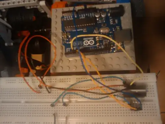
Here's a picture of what I built: Picture

Matt
  • 619
  • 3
  • 10
  • 14
  • 3
    Photo is better than some but could be sharper and brighter. As the problem MAY be how you connect a pin that you think is OK but isn't then a crisp clear photo may be what makes the difference. MUCH more light will help your camera greatly. If using a phone camera be sure it is in focus before capturing. Detail around the IC with where each wire goes being clear would be helpful. – Russell McMahon Aug 17 '12 at 01:07
  • 4
    Drawing your COMPLETE circuit diagram as You think that YOU have made it will also be of use. As the two diagrams you provided are not identical and your notes suggest you have "tried" an idea from one on the other, it is not certain what you think you have actually done. The circuit is actually very simple despite it appearing slightly confusing and a dead IC or dead drive port or wrong connections are the most likely problem. – Russell McMahon Aug 17 '12 at 01:19
  • @Russell - Thanks for pointing the package thing out. Rather silly of me not to check the datasheet really... – Oli Glaser Aug 17 '12 at 12:01
  • @OliGlaser - easily done and datasheet does not make it overly clear. I've met these packagess before in this sort of context. What I want is a CLEAR photo so we can be SURE of what wire goes where. – Russell McMahon Aug 17 '12 at 14:51
  • Matt - Are you grounding pins 1 & 15 if a current sense resistor is not used? If pin 1 is not grounded it will; not function. – Russell McMahon Aug 17 '12 at 14:52
  • I would double check for common grounding – chwi Aug 24 '12 at 21:20
  • Have you solved that problem? I have the same, the power suply is 12V but output get 3V and max 0.8A (normally motor runs with 2A) –  Dec 13 '12 at 16:52
  • Also, the Enable input should be a digital logic 1. There's no advantage to using an analog 4V signal there, and it could potentially cause problems if the output has insufficient current drive capability or if the voltage is too low. The lack of a common ground and current sense pins left floating or with too high a resistor in place is probably what's making your circuit not work, though. – Chintalagiri Shashank Jan 26 '13 at 07:14

2 Answers2

1

Hmm. I actually selected this question from the suggestions on the sidebar. I did not realize its a year old!

Tie the enable pin to 5V for now - in this way the speed will just be constant. There is no need to try and fiddle with speed until you get the device working properly.

It's hard to decipher what is going on based solely on the picture provided - I would consider drawing up the diagram and posting it instead. Also, post the code.

Now, considering the datasheet you can find this diagram:

enter image description here

As you can see, if you do not have the motor in place (between OUT1 and OUT2) then it makes sense that one of the pins is very close to 0V potential. Now, the other pin being at approximately the same voltage is an issue.

Set IN1 to 5V, IN2 to 0V, ENA to 5V, and Pin1 (current sense) to ground (assuming you are using the left bridge) and see what happens (the upper left AND gate and the low right AND gate should be on). OUT1 should now have Vs (~12V in your case) when OUT1 and OUT2 are open circuit.

Once you get this far you are on the right track.

I am currently having a similar issue with my L298, so I cannot finish this answer but at least can provide guidance.

sherrellbc
  • 3,431
  • 6
  • 35
  • 62
-1

You must use a separated power supply for the bridge, and this must be attached to the arduino ground

egwyn
  • 1
  • 2
    This is incorrect. It is possible to run a low-current stepper off the same supply the Arduino regulators are run from without any trouble. Depending on the motor, you might have noise issues, but that can be dealt with when/if it becomes a problem. – Connor Wolf Aug 30 '12 at 07:51