I'm working on a circuit powered by a capacitive transformerless power supply, that is a microcontroller based triac-switching project for resistive loads.
I've taken the basic design of the power supply from Microchip's Application Note AN954:
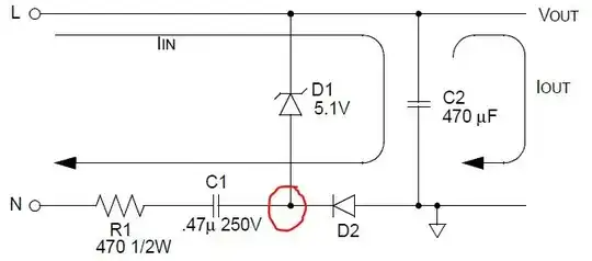
I'm using 1uF for C1 and 5.6V for D1, as they allow for a slightly increased load. I'm also in the UK so it's powered by 240v @ 50Hz.
I've attached an interrupt pin on the microcontroller to the point circled in red on the schematic via a 100K resistor, to give me the ability to detect the zero crossing. However, as this is a capacitive power supply, the zero crossing point detected is out of phase with the real zero crossing.
If I simulate the circuit, I can see that it's approximately 270° out of phase, however I'm not sure if this is just by chance based on the component values I've chosen, or if this circuit would always produce a zero cross exactly 270° out.
Is there a way to calculate mathematically (not too advanced!!) exactly what the offset is, so that I can accurately compensate for it in the firmware?