If I were wanting to drive i.e. industrial relays which require 24v from a Microchip PIC what would I need to look at in terms of a general transistor circuit (and it's pitfalls when driving such a component).
Asked
Active
Viewed 1.8k times
4
-
1_'Controlling a relay from a microcontroller'_ This question has been asked so many times here. Steven, Olin.. are you in for a nice canonical answer? :-) – m.Alin Aug 16 '12 at 17:16
-
Apologies if this is repeat (I did do a search but was too specific I think) – Paul Sullivan Aug 16 '12 at 18:00
-
2Related questions: http://electronics.stackexchange.com/questions/33287/choosing-a-relay-to-control-outlets-from-arduino | http://electronics.stackexchange.com/questions/15960/need-advice-on-microcontroler-to-switch-relay-on-off | http://electronics.stackexchange.com/questions/25673/driving-a-relay-directly-with-a-microcontroller | http://electronics.stackexchange.com/questions/35478/driving-solenoids-from-arduino – m.Alin Aug 16 '12 at 18:13
-
1@m.Alin - you're right, it needs a canonical question/answer that includes things like a discussion of the transistor specs and the inductive factor. It's certainly a popular one, I recall answering quite a few similar questions. – Oli Glaser Aug 17 '12 at 03:54
-
Will do @stevenvh - It will also give me some time to digest your answer (much appreciated btw) and some of it's intricacies :) – Paul Sullivan Aug 17 '12 at 16:28
4 Answers
10
I'm sorry, but I think Matt's answer is not a good one at all.
The MOSFET in his schematic is a P-channel, not an N-channel. The diode doesn't offer any protection for the FET; it may be destroyed together with the FET. Besides it's a 20 V diode, so even if it would protect against the induction voltage the 24 V supply may already kill it. The 7406 is superfluous, besides its maximum voltage is 30 V, not 40 V, and that 30 V is Absolute Maximum Ratings, not for continuous use. The circuit will also draw an unnecessary 5 mA with the relay on, and 10 mA no less with the relay off. Also the 100 Ω resistor doesn't "dampen oscillations".
What you need is a logic level gate MOSFET. You're using a PIC, which probably will have a supply voltage of minimum 3.3 V. Let us know if the voltage is lower. A logic gate FET will switch on with a 3.3 V gate voltage, so the PIC can drive it directly. No 7406 needed.
A relay typically needs less than 500 mW, at 24 V that would be 20 mA, but this is an industrial relay, and will probably need more. Let's be generous and say it needs 1 A (that's 24 W!). If we can find a FET with an \$R_{DS(ON)}\$ of less than 350 mΩ we'll be able to use an SMD; these are much cheaper than PTH parts. At the high 1 A it will dissipate 350 mW. What else? Power supply is 24 V, so let's take a maximum \$V_{DS}\$ of minimum 40 V. One FET which fulfills these requirements is the BUK98150:
Max. \$V_{DS}\$ 55 V
Max. \$I_D\$ 5 A
Max. \$R_{DS(ON)}\$ < 200 mΩ @ 3.3 V
Max. \$V_{GS(th)}\$ 2 V
Looks good. The BUK98150 will sink 2 A at 2.6 V gate voltage.
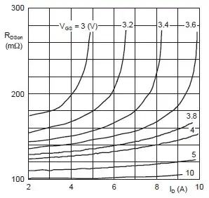
This graph shows an \$R_{DS(ON)}\$ of 175 mΩ @ 3 V and 2 A, for 1 A it will be less. Then dissipated power will be 175 mW, which the SOT-223 package can handle easily. The 175 mV drop is negligible.
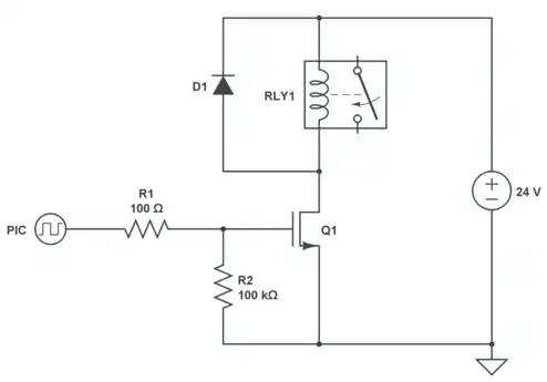
This is the circuit. Contrary to Matt's it only consumes 0.1 mW. I've kept his 100 Ω resistor, which limits the short current spikes when switching; a microcontroller doesn't like capacitive loads much. The 100 kΩ ensures that the gate won't float if the PIC's I/O would be switched to input accidentally.
As you can see the diode goes over the relay, not the FET. You can use a Schottky diode here. This one has a maximum reverse voltage of 40 V.
stevenvh
- 145,145
- 21
- 455
- 667
-
Only question and it's really an 'aside'. Choice between p-n diode and Schottky is purely due to high frequency capability of the Schottky? If the lag in a p-n diode is irrelevant then p-n is fine? I don't see a reason why you would need a Schottky as a flyback (correct my ignorance if you will) – Paul Sullivan Aug 17 '12 at 17:49
-
and, and, and... how does anyone find components with specific characteristics so quickly (just experience or are there specific places you look?) – Paul Sullivan Aug 17 '12 at 18:03
-
@Paul - Schottky's have a faster recovery time, but that's actually only relevant if you want to switch on quickly after switching off. In most cases for low currents a 1N4148 or for a bit higher a 1N400x will do. A Schottky also has a higher leakage current, esp. at higher temperatures, but still will be only a fraction of what the relay needs, so no worries. Always check the reverse voltage, though: for Schottky's that's often more limited. – stevenvh Aug 17 '12 at 20:47
-
@Paul - I almost always use the selection tools on the Digikey site. Of course you have to understand what different parameters mean to be able to select a value or range for them, and that's experience. More often than not you still have enough parts to choose from, and then it's browsing through a couple of datasheets. Digikey has links to datasheets for 99.999999999 % ;-) of their parts. (Just one or two missing, that is) – stevenvh Aug 17 '12 at 20:51
-
thanks @stevenvh I was going to use a 1n4001 though I will check it's specs properly and make sure I'm not over stressing/volting. I will bookmark digikey. Thanks a lot for your help I have to say you are an ambassador (having seen your major contrib on many other questions) to electronics.stackexchange. Much appreciated – Paul Sullivan Aug 17 '12 at 22:02
1
I personally would follow stevenvh's answer only I would move R2 to the pic side of R1. The reason for this is R1 and R2 are acting as a voltage divider and therefore you are not getting the full pic voltage on to the gate pin of the MOSFET. by moving R2 to the other side of R1 you'll get the full voltage at the gate pin. Admittedly the voltage loss will be very small as the resistor values chosen here will only loose 0.003v @ 3.3v so it wouldn't really make a difference in this example but with different resistor values it could make a difference so out of principle I would always put R2 on the other side of R1
user33917
- 11
- 1
0
I recently did something very similar to this as a beginner, and found MOSFETS very useful. You need a 24V source from somewhere to switch your relay, which should be connected across the drain-source pins of the MOSFET. You apply a voltage to the Gate pin (using the pinout from your PIC), and this essentially switches the relay-driving circuit on.
I made the mistake of taking the gate-threshold voltage in the datasheets as the voltage required to fully turn it, so rather than worrying about this it's much easier to just get a logic-level MOSFET, such as the IRL520. You need to make sure that it's capable of switching 24V and whatever current your relay will draw.
You also need to connect a diode in parallel with the relay to prevent damage to the transistor when it switches.
Matt
- 194
- 1
- 1
- 12